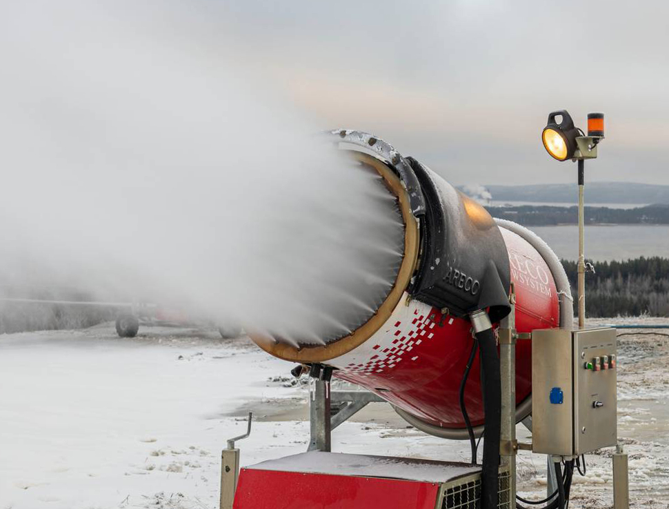
When the environmental conditions are correct, water can be atomized to form the nucleus of a snow crystal.
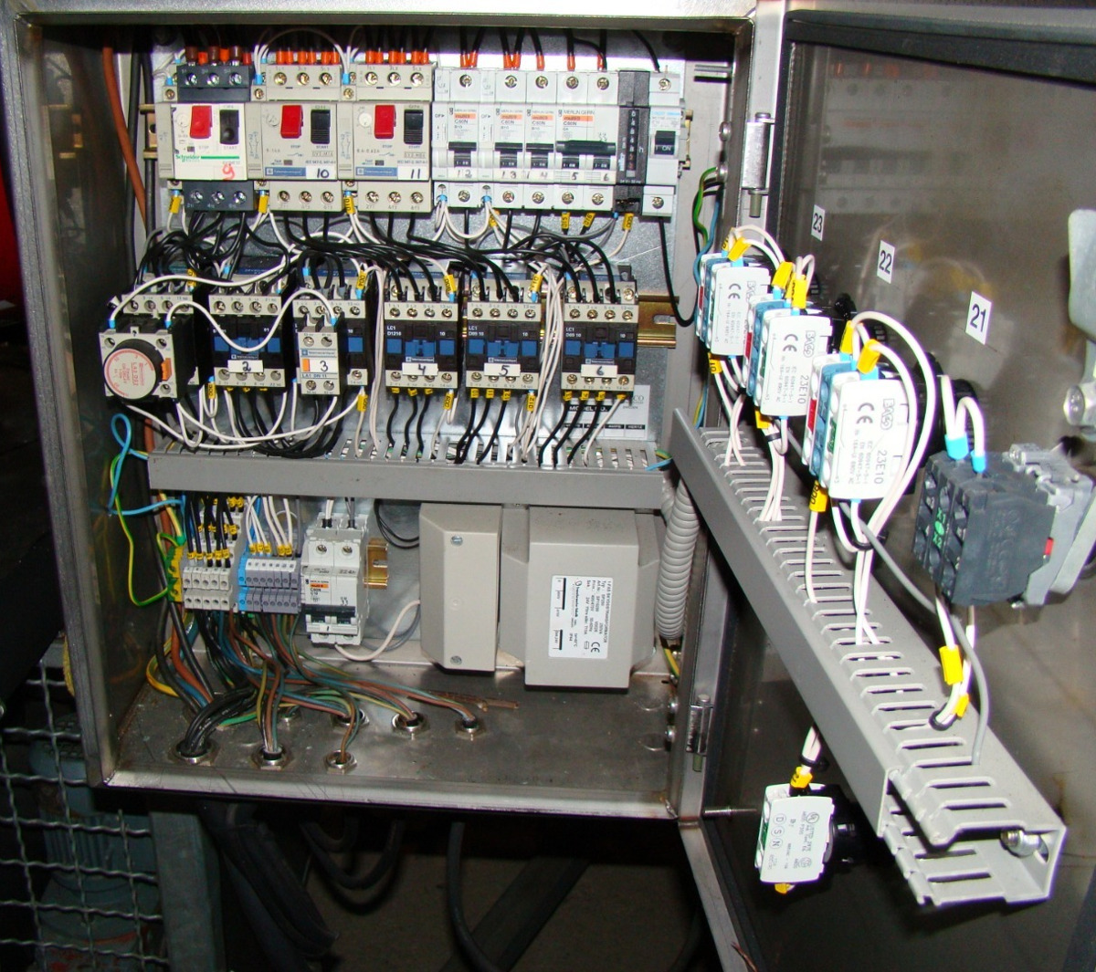
The metal box contains electrical switches and relays. A second box (not visible) contains the control computer and radio modem.
A ski resort had an aging snow making system that was starting to have some reliability issues. They only had basic knowledge of the system functionality and the manufacturer no longer supported the product. However by reverse engineering the system’s behavior I was able to identify the faulty components and develop an improvement plan. The legacy Windows-based GUI was augmented by a SCADA system.
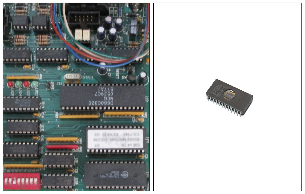
There was minimal documentation available for the system, given that most large systems like this are customised, however we did have complete circuit and wiring diagrams for the machines. The snow-making fanguns have various inputs and outputs, including a water pump, heater, blower fan and air nozzles. The on-board computer utilises a Dallas DS80C320 (8051 compatible) Microcontroller and M27C256B UV EPROM (Ultra-Violet Erasable Programmable Read-Only Memory) chip (Fig. 3). This technology is deprecated by today’s standards, but at least it was easy to debug. Similar hardware can be found in old Poker (Slot) Machines and Arcade Games.
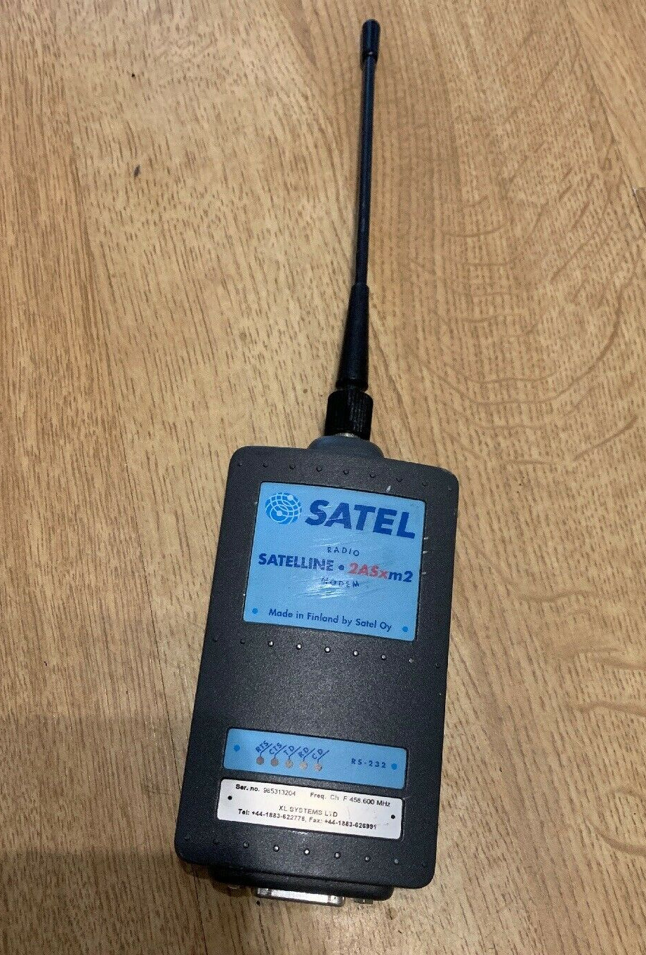
Each snowgun has software consisting of a control program and temperature parameters “burnt” onto the EEPROM chip (Fig. 3). Producing snow is as simple as setting the snowgun to “automatic” mode, assuming the weather conditions are appropriate. An operator has to manually hook-up the water and turn on the heater, but the snowgun receives operational commands from the Base Station via a Satel UHF radio modem (Fig. 4).
It was relatively easy to reverse-engineer the embedded software for the snowgun because it was originally written in assembly language. The control code was downloaded from the snowgun’s EPROM chip and then using the circuit diagram I could methodically determine exactly what the program was doing and what were the configurable parameters.
Ultimately, I verified the system’s correct operation, replace some unreliable components and make some modifications to the software program. Most of the operational problems were due to radio signal interference and aging hardware. I developed a test program to measure the radio signal strength in each location. Other intermittent problems were due to moisture ingress or thermal-cycling of the electronics.
 |
 |
 |
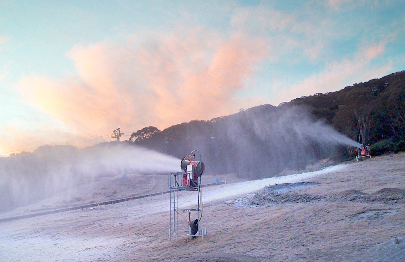 operation, producing artificial snow. The coldest temperature is often at sunrise. |
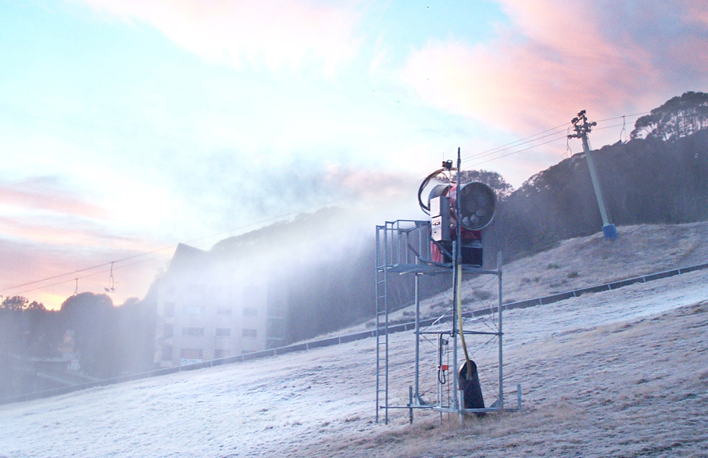 The radio antenna is on top of the pole. One metal box contains the on-board computer and radio modem. The other box contains the electrical switchgear. |
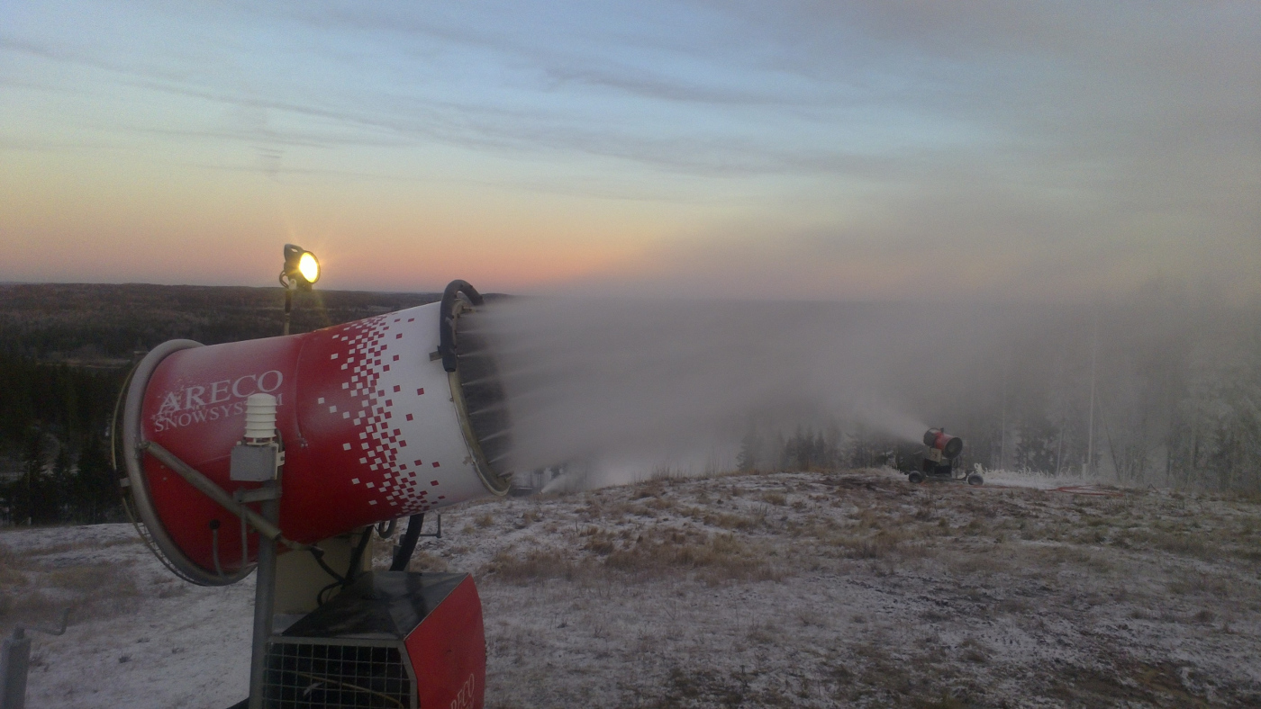 The white plastic shroud contains sensors for temperature, humidity and wet bulb. |