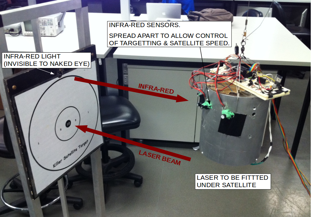
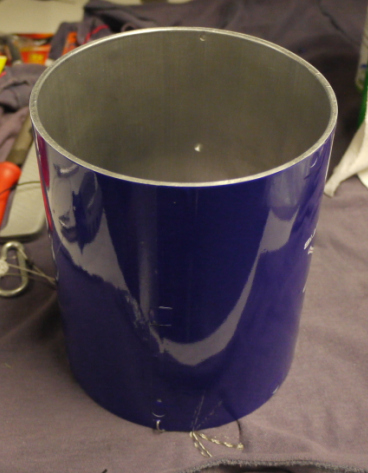
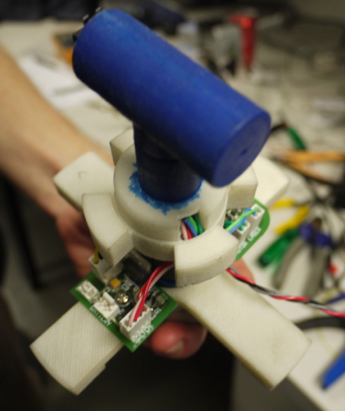
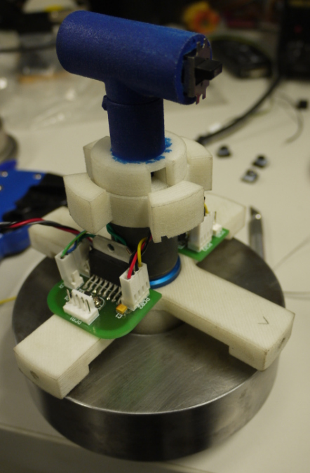
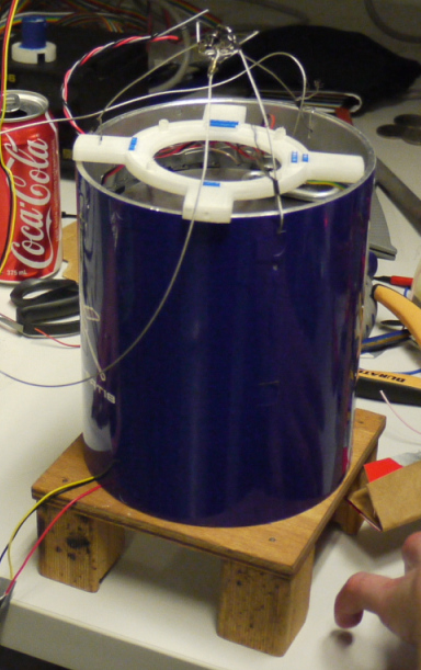
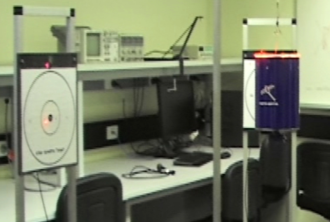
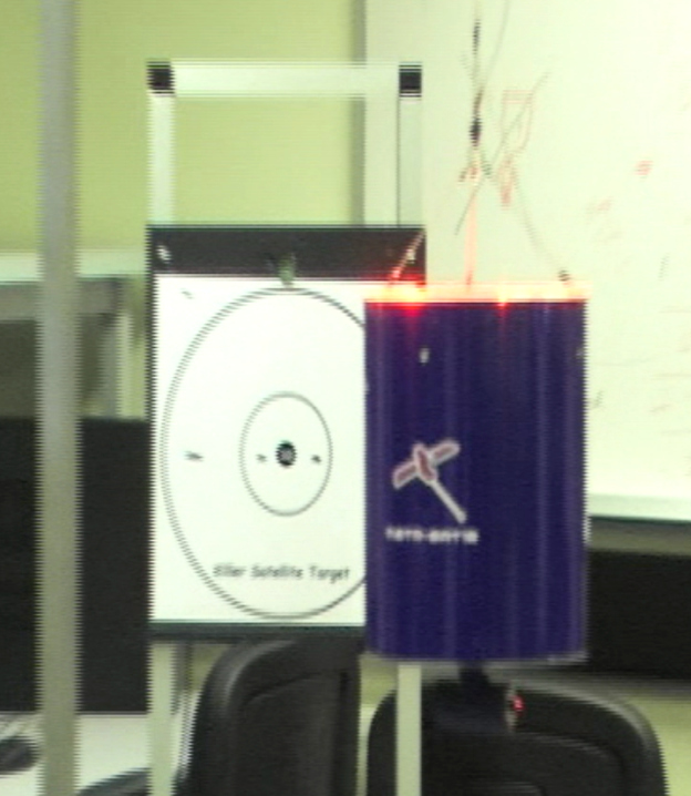
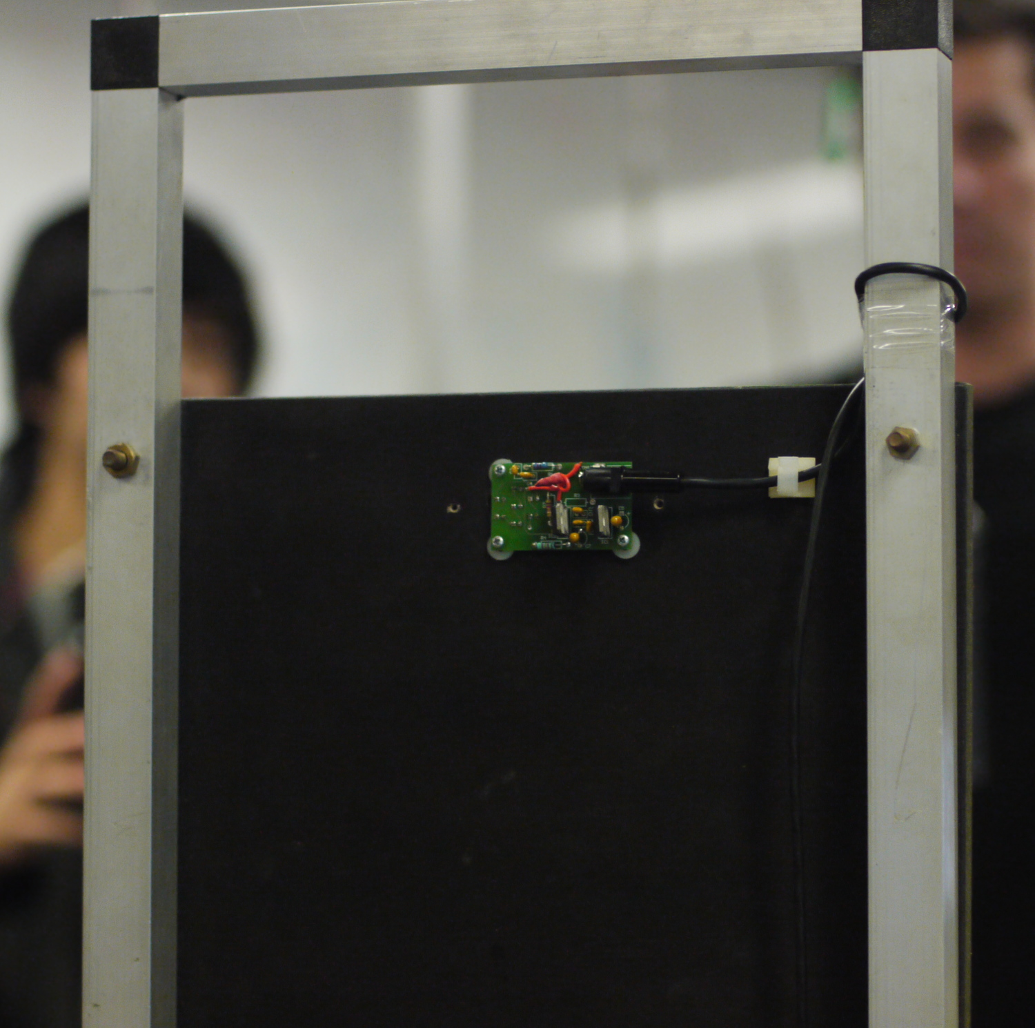
This project was to build a single-axis working model of a space satellite for defense (defence) purposes. The image below (Fig. 1) shows the system in operation. The satellite is the blue-colored cylinder which is hung from a thin wire cable. The satellite can rotate itself left or right around the vertical axis in order to find targets and shoot them with a laser. Each target consist of a paper bull’s-eye with an IR (Infra-Red) light above the outermost circle. The satellite detects the IR light and tries to mark the bull’s-eye with a laser. For the demonstration, each target was remotely turned “on” or off” in sequence and the satellite would try to hit whichever target was activated.
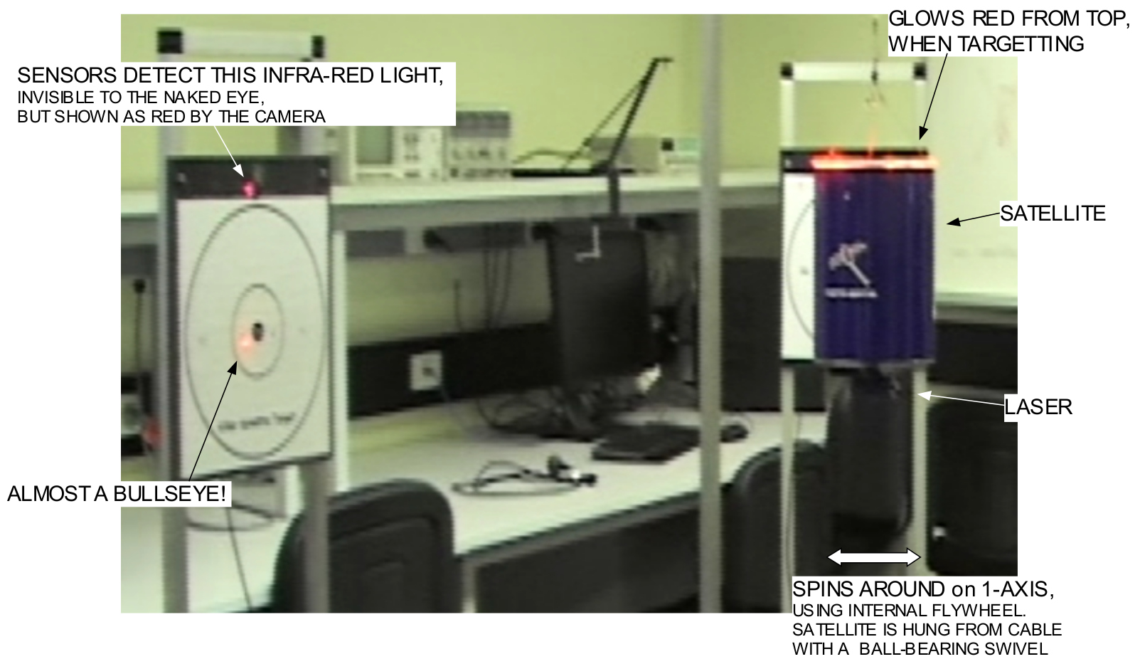
(screen capture from video)
Theory of operation
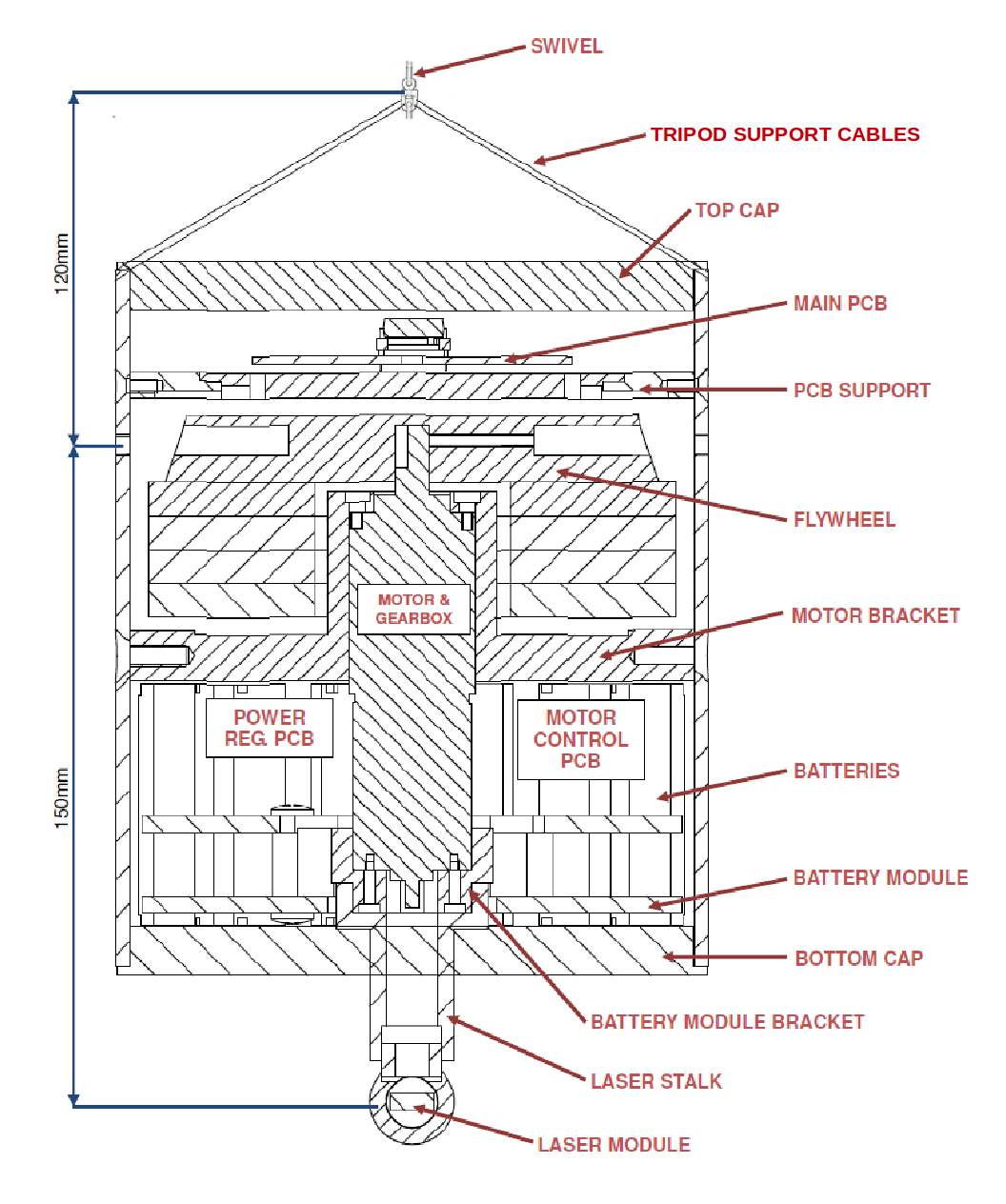
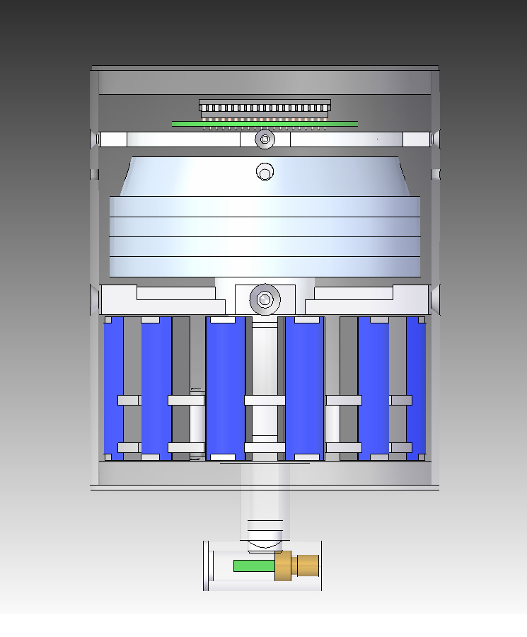
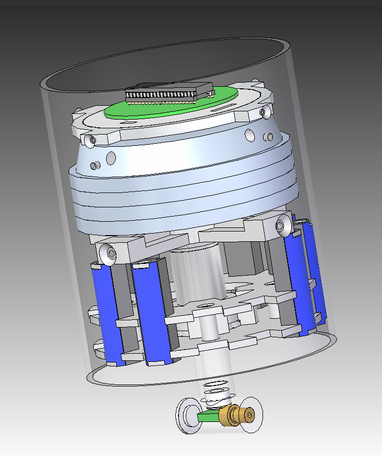
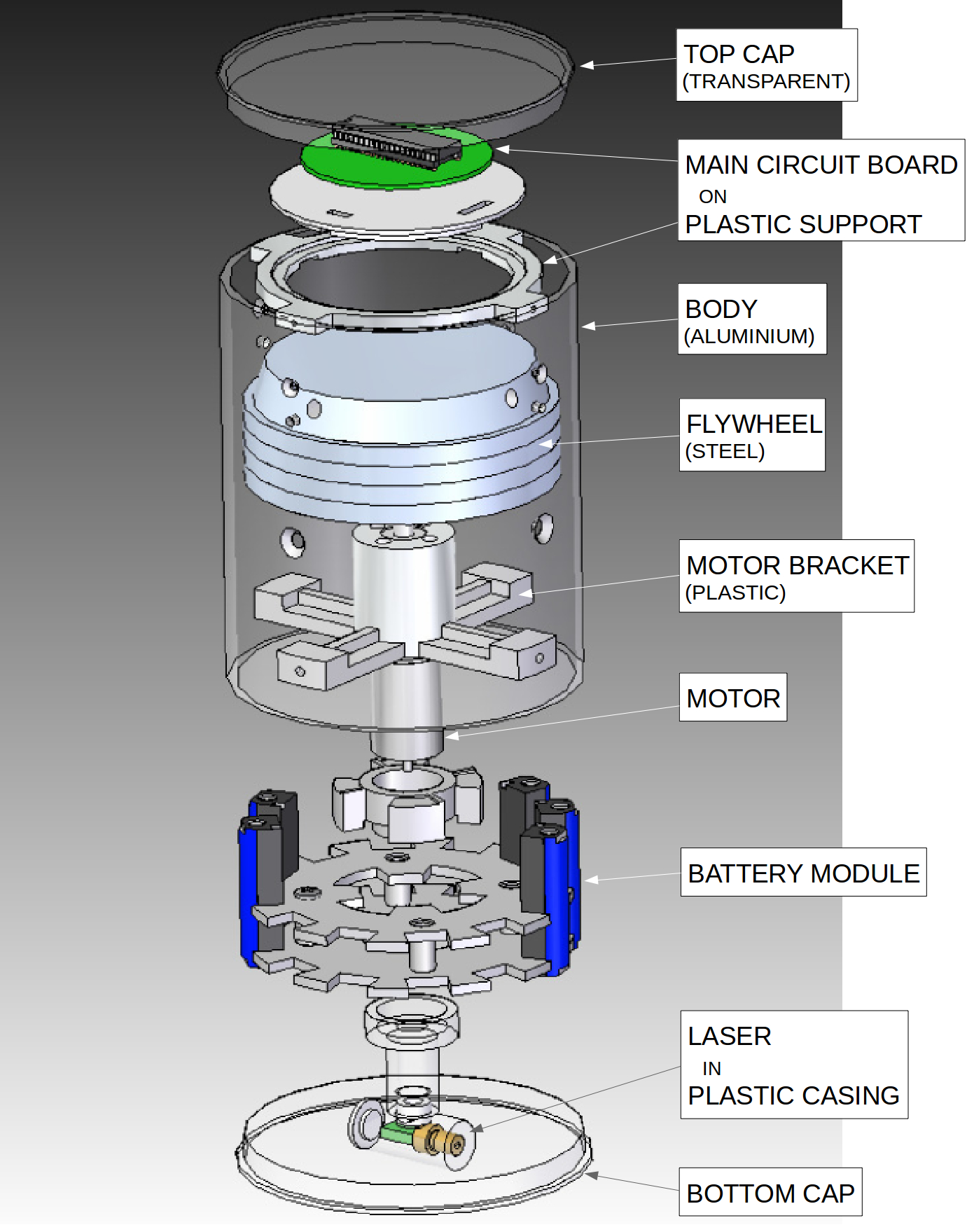
The satellite is essentially an aluminum (aluminium) can containing a motor and steel flywheel. The satellite uses the flywheel, called a “reaction wheel” to spin on one axis. This is the same concept used to adjust the attitude of satellites in space, like NASA’s Kepler telescope. If the motor applies a torque to the reaction wheel, the law of conservation of momentum states that the aluminum can will rotate in the opposite direction.
Demonstrations
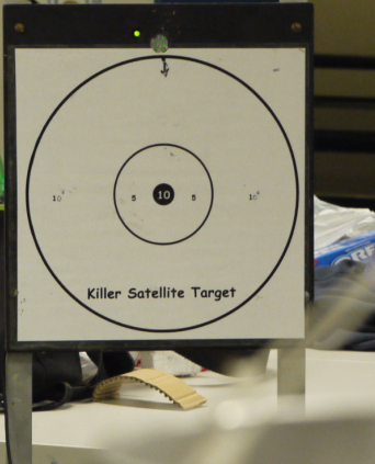
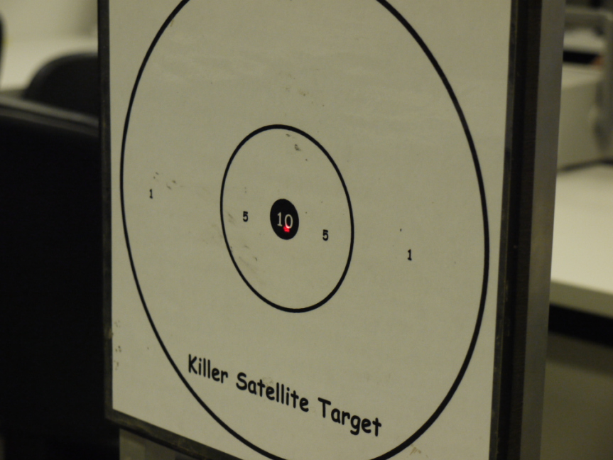
Two demonstrations of the satellite defense system were conducted. In the first demo (see Video 1 below), the goal was to shoot as many targets as possible in 5 minutes. There are 4 targets that each have an IR (Infra Red) LED located above the target circle. The satellite uses an array of photo diodes to detect the IR light and fires a 1 milliwatt red-colored laser to mark the paper target. A bull’s-eye is worth 10 points, within the inner circle is 5 points, and within the outer circle is 1 point.
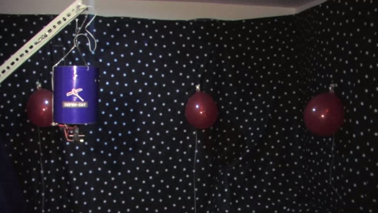
In the second demo (Video 2), the paper bull’s-eye targets were replaced by balloons. Each target is illuminated in sequence and the satellite uses a high-power U.V. (Ultra Violet) laser to burst the balloons. For more details about this experiment, see the end of this page.

Warning: Don’t try this at home, lasers are not toys. This experiment was performed in a controlled environment whilst wearing appropriate PPE (Personal Protective Equipment).
 Video 1: Demonstration of defense satellite using a 1mW 650nm laser to mark targets. |
 Video 2: Second demonstration where the satellite has been fitted with a 1W 445nm laser to burst balloons |
The remainder of this page describes the process to design, prototype, manufacture, test and program the satellite. The design of the final product illustrates that a tightly-integrated mechatronic system requires multidisciplinary knowledge of electronics, mechanical design and computer software. Sometimes an engineering problem can be solved either using more advanced software, or by adding an extra circuit, or by modifying the mechanical design; so it’s important to consider multiple solutions.
Design Process
of the proposed satellite design.
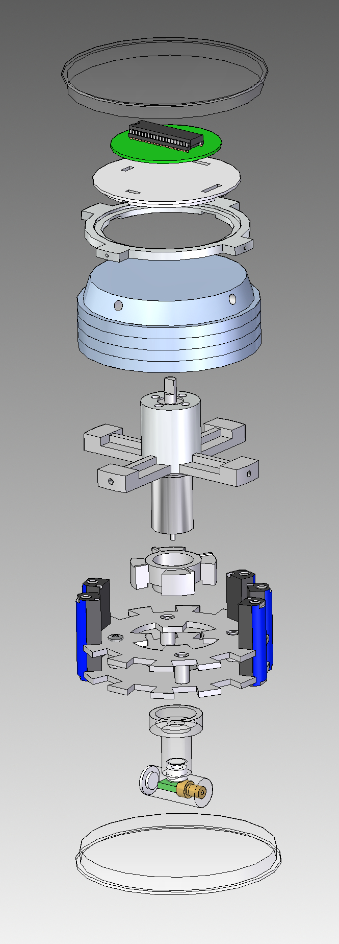
1. Various design ideas were sketched on paper. The final design is shown in Figure 2.
The design was constrained by the size of the satellite body which was specified as an aluminum tube of dimension:
170mm tall, 143.24mm O.D. (132.96mm I.D.)
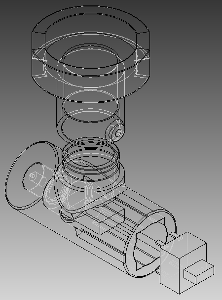
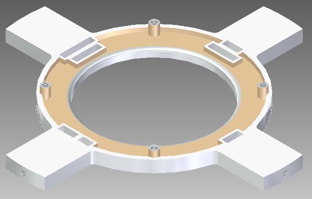
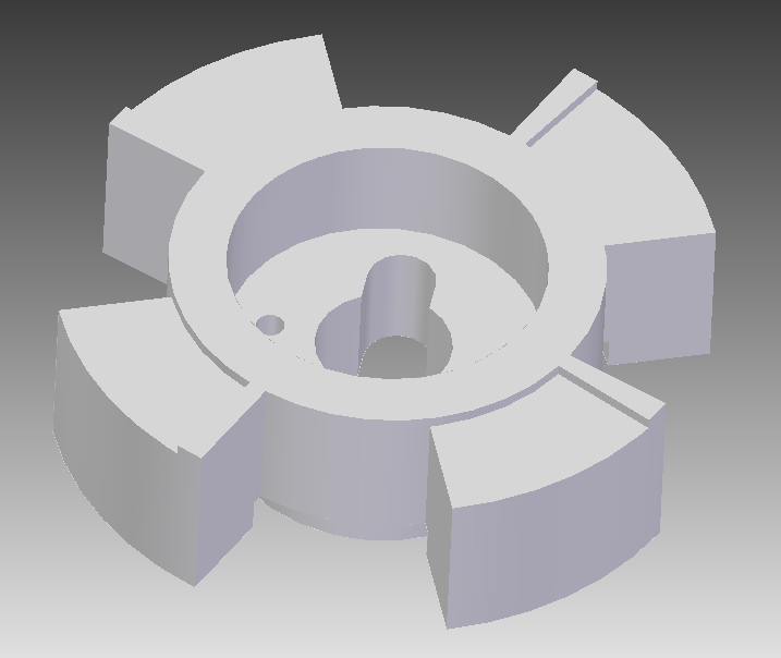
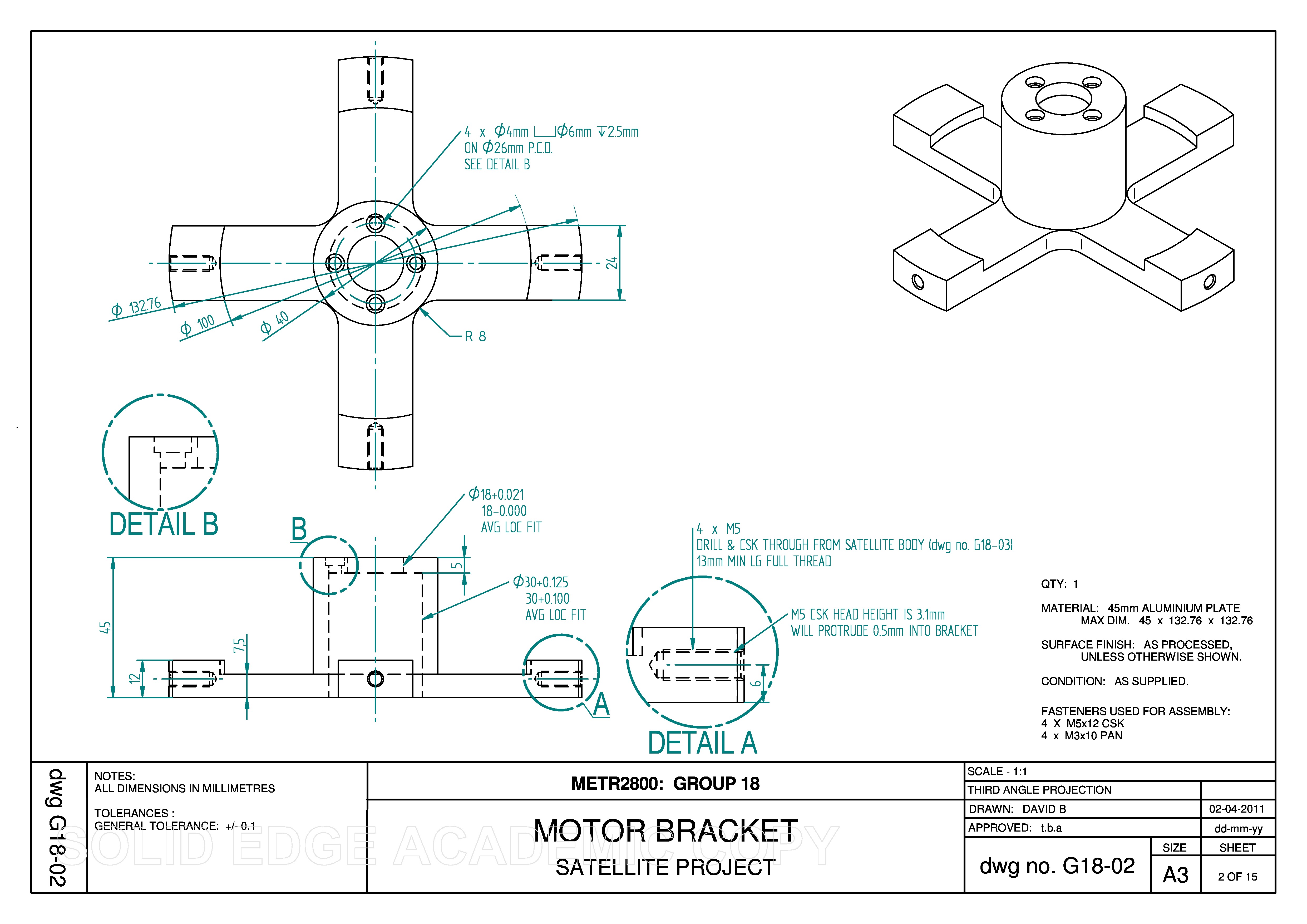
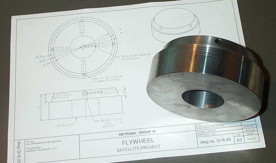
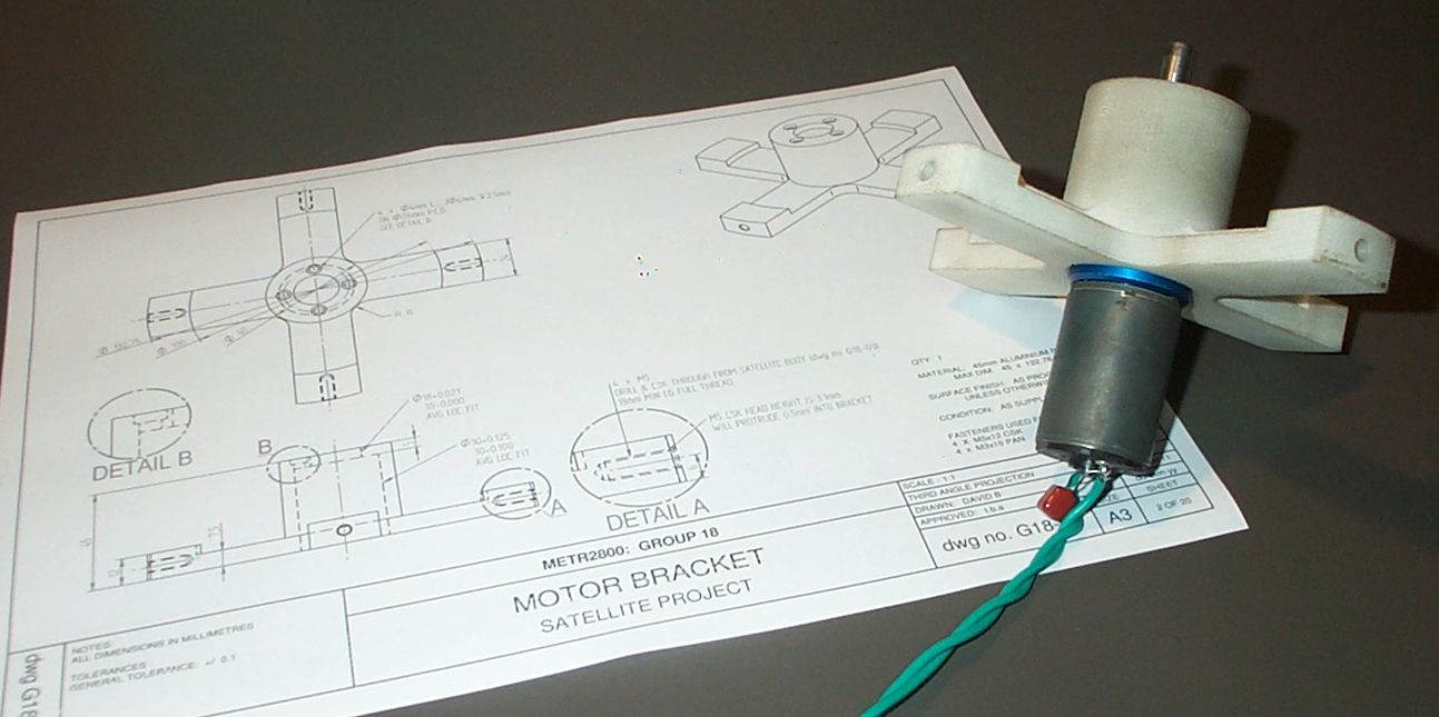
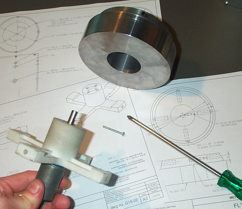
The steel reaction wheel was calculated to be of a mass that dictated that it would occupy a significant volume of space (See the design report for calculations). One option was to make the reaction wheel a solid disk and mount it to the end of the motor. An alternative option, that we used, is to hang the reaction wheel around the motor (Fig. 2). This design is more space-efficient, however it requires a more complex bracket to attach the motor. The motor is attached to the body using a cantilever bracket.
The height of the cantilever bracket was constrained by the decision to locate the batteries between the underside of the bracket and the bottom cap of the satellite. There are 12 x ‘AA’ size NiMH (Nickel-Metal Hydride) batteries that provide at least 14 volts direct to the motor. This was the maximum number that could be arranged around the circumference of the satellite body. A second voltage tap at 9 volts is used to supply the electronic circuits.
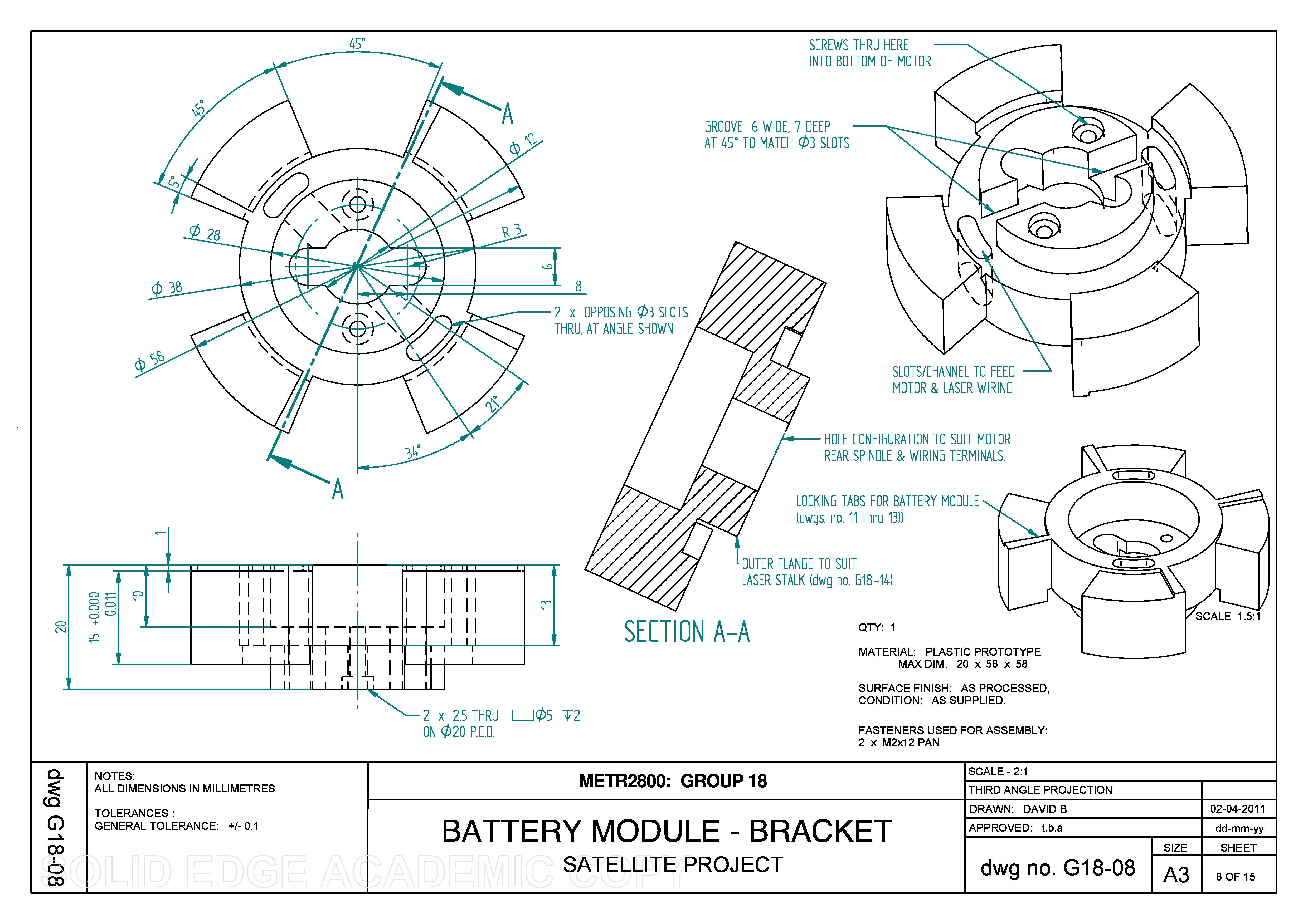
The individual batteries are integrated into a battery module. We could have mounted the batteries permanently to the satellite body, and re-charged them internally, however we calculated that we would need a long time to test the prototype. Therefore we designed a replaceable battery module that is attached using a friction-lock bracket on the bottom end of the motor.
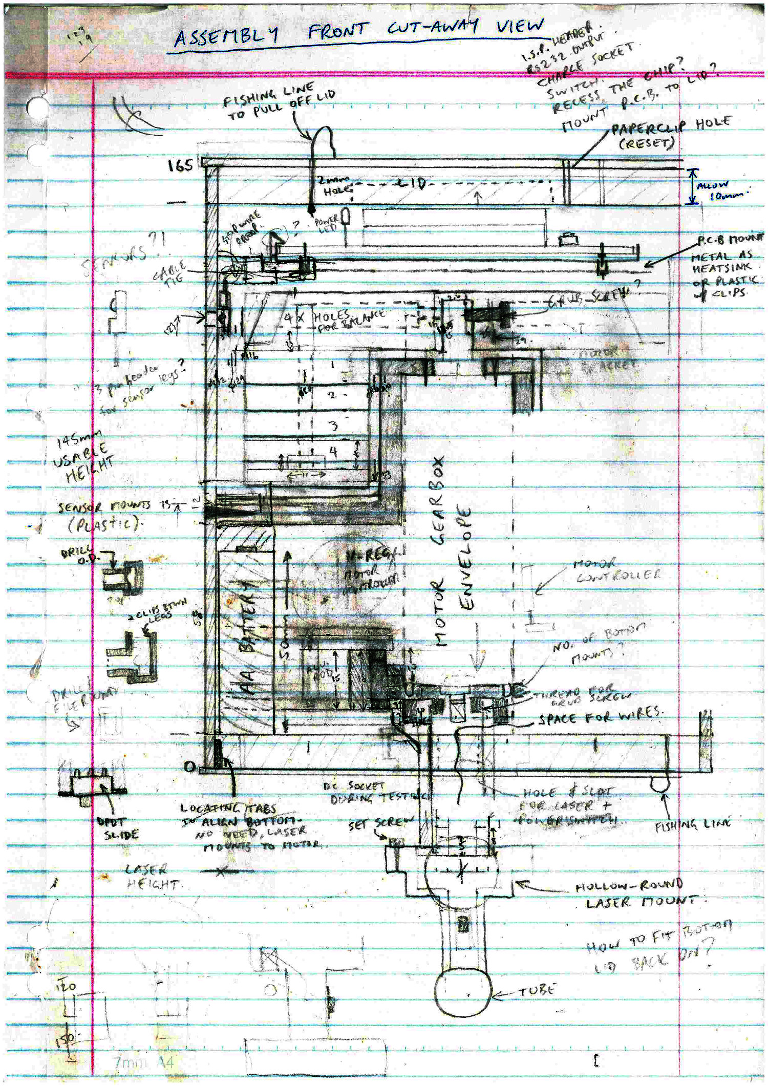
Sufficient space was kept between the top of the reaction wheel and the top cap of the satellite. This space had to accommodate the height of the main PCB (Printed Circuit Board), the tallest component being the microcontroller chip installed in an IC (integrated circuit) socket, and a bracket to attach the PCB to the satellite body.
Additional PCBs were located between the motor and the batteries. Positioning the motor controller in this location means that the 14 volt wires from the batteries to the motor are the shortest length. The tallest components that had to fit in this space are the motor H-bridge chip and the 5 volt regulator chip, although we did not use the most low-profile versions of these ICs.
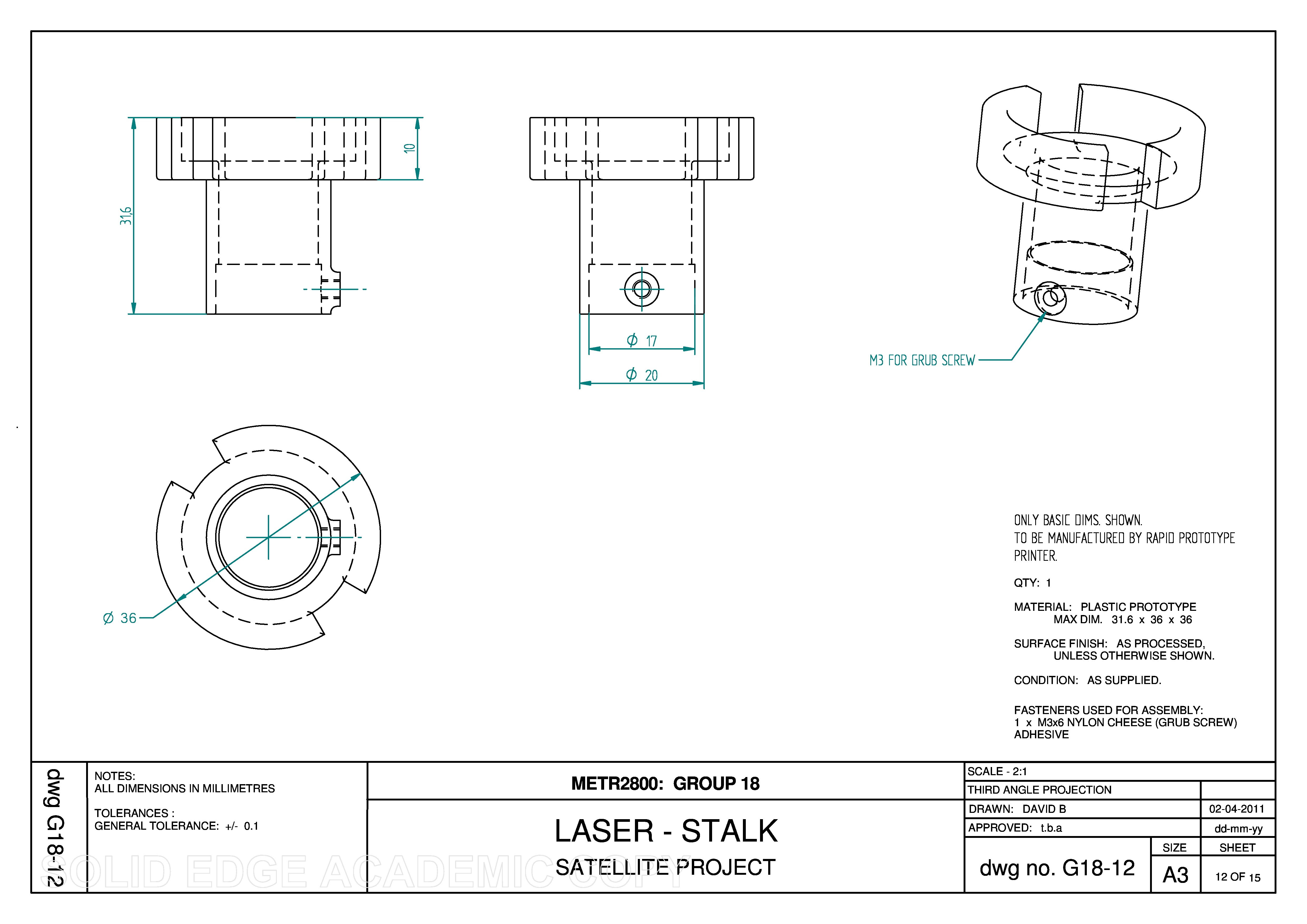
The laser is mounted to a plastic stalk that protrudes through the bottom cap of the satellite. The stalk is permanently fixed to the bracket at the bottom end of the motor.
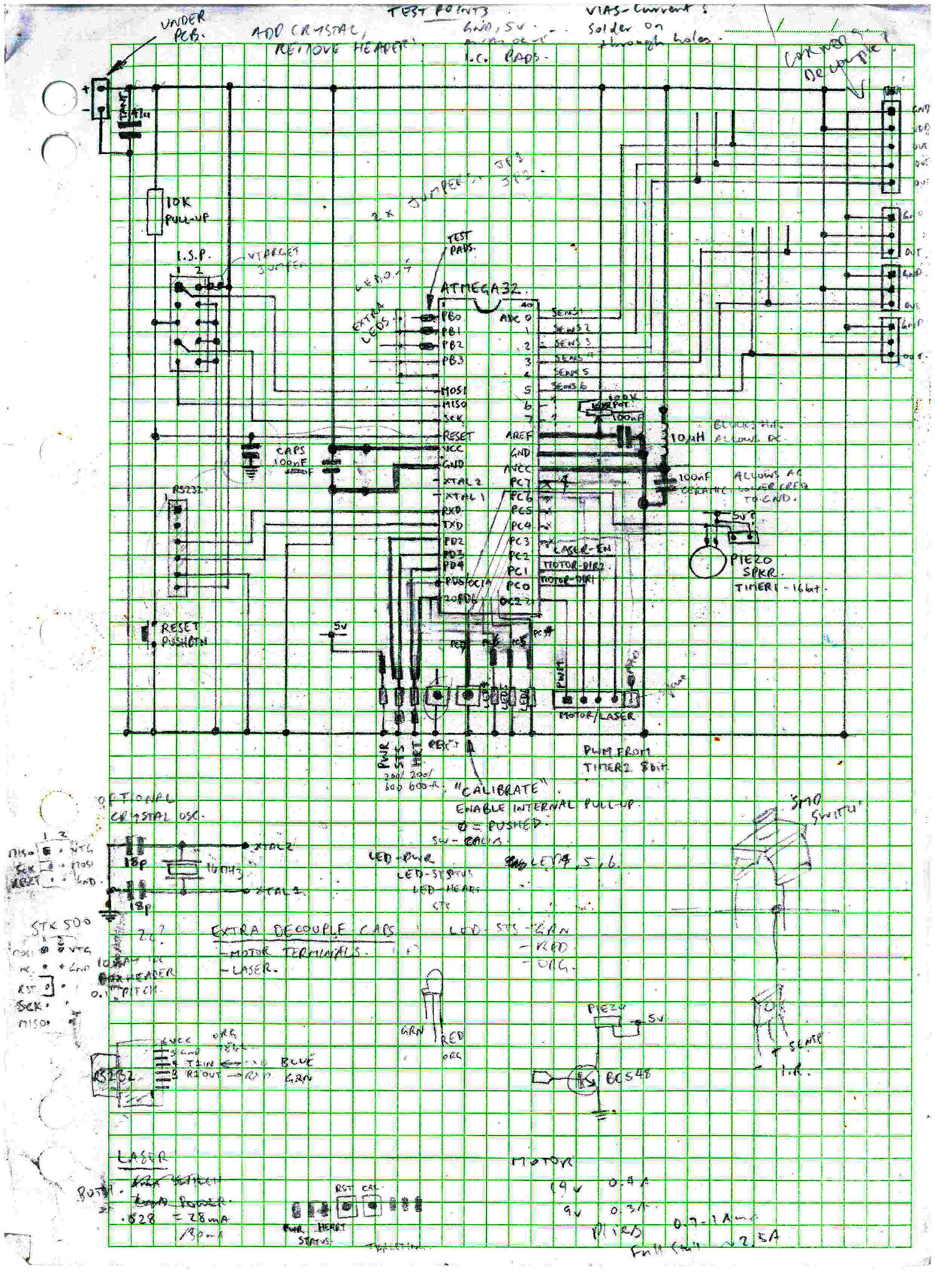
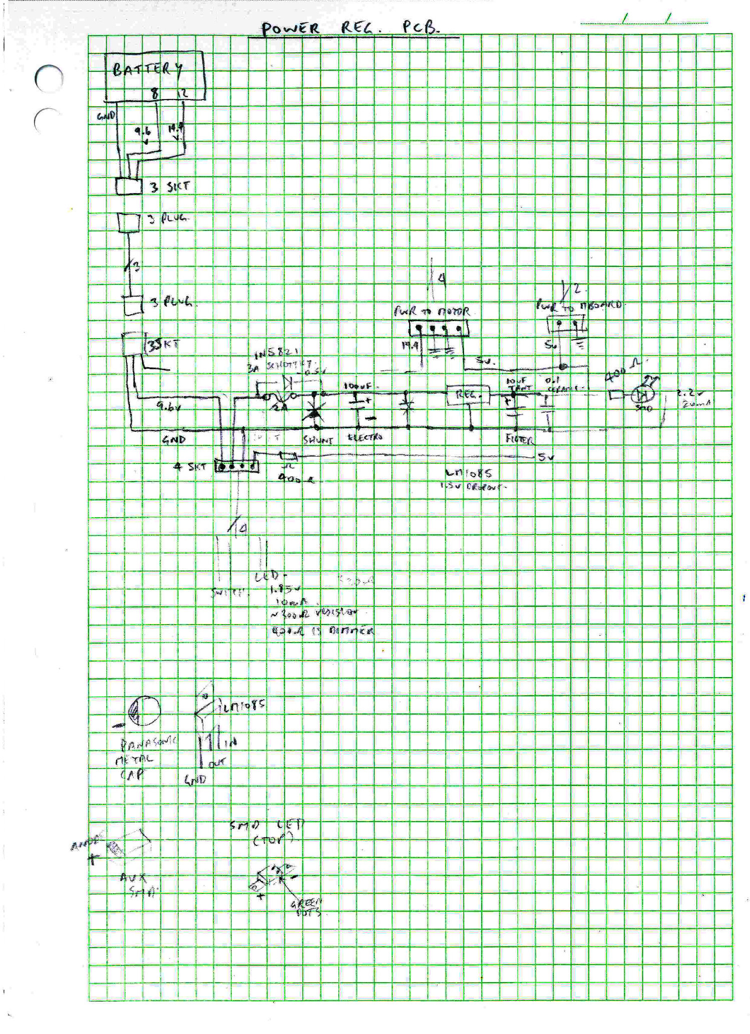
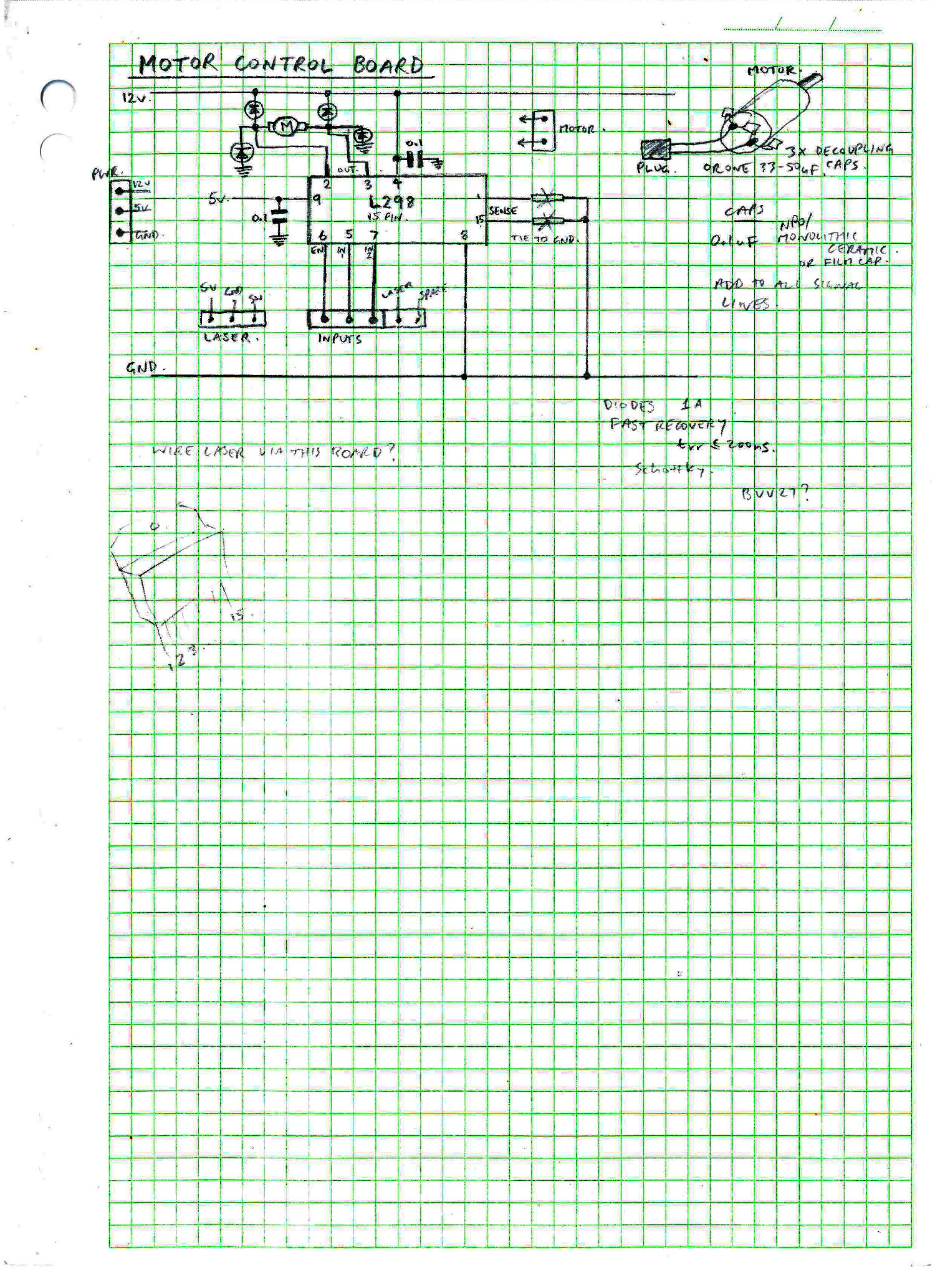
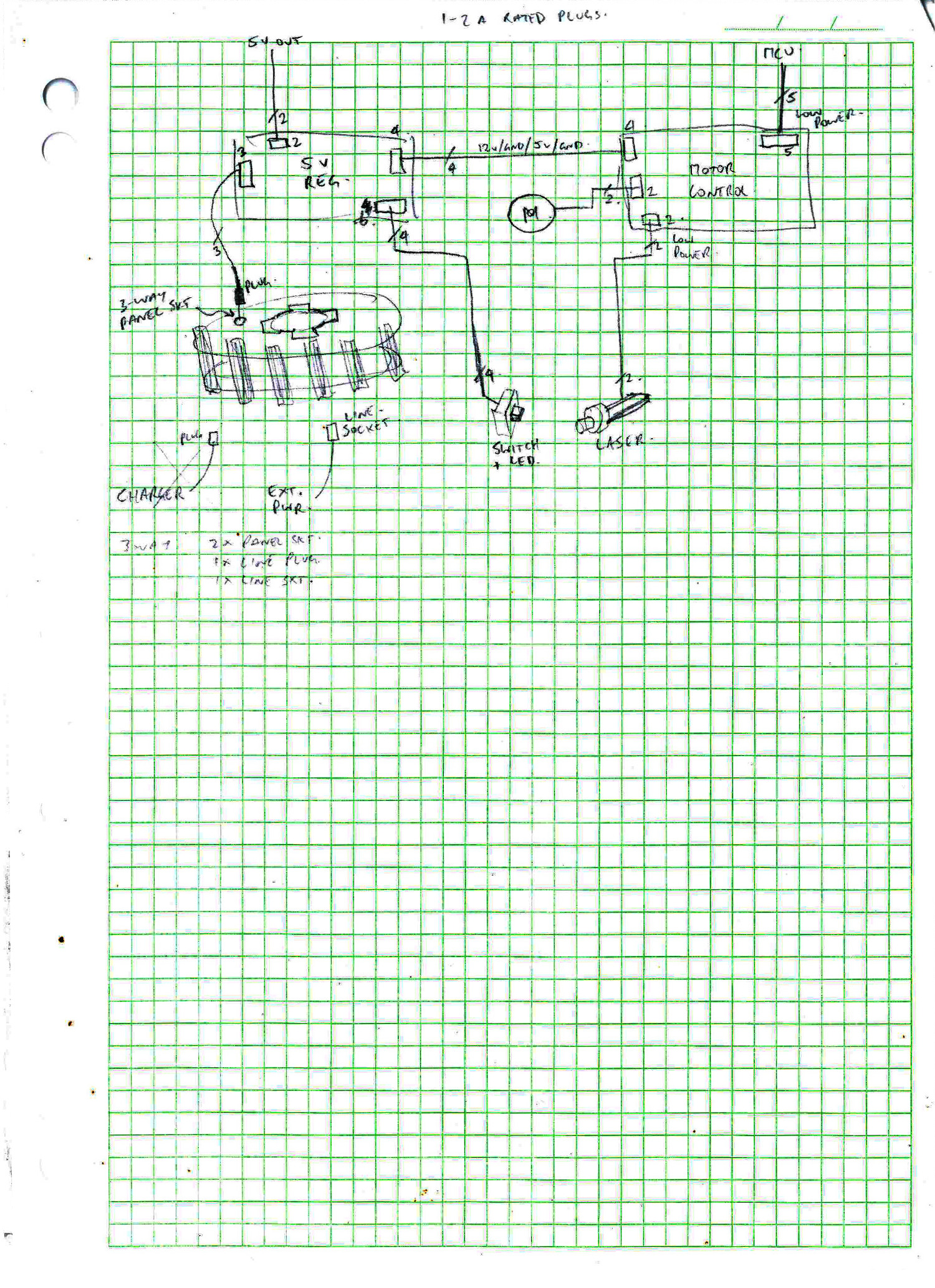
2. The required electrical circuits were designed using a combination of reference designs, theoretical electronics principles and previous experience. The final designs were drawn on grid paper (Fig. 3 – 6) so that prototype circuits could be assembled using perforated stripboard or solderless breadboard.
 |
 |
 |
 |
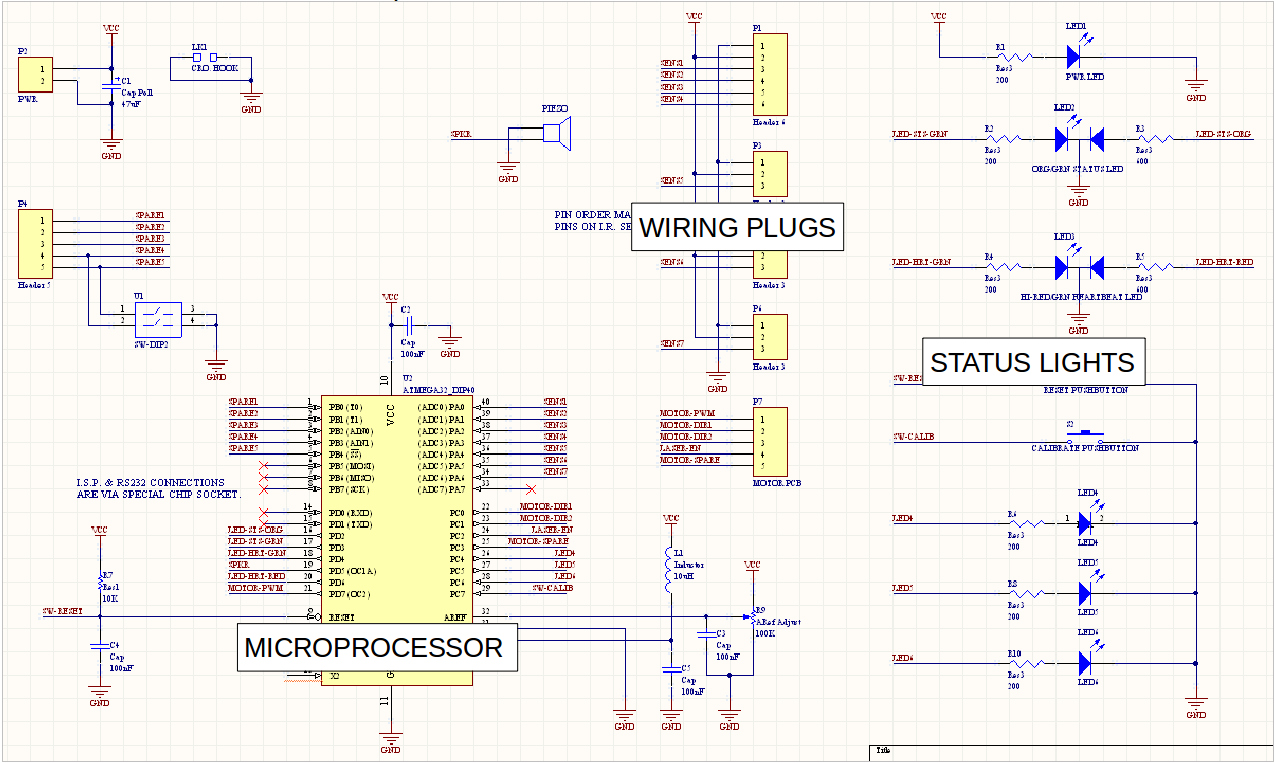
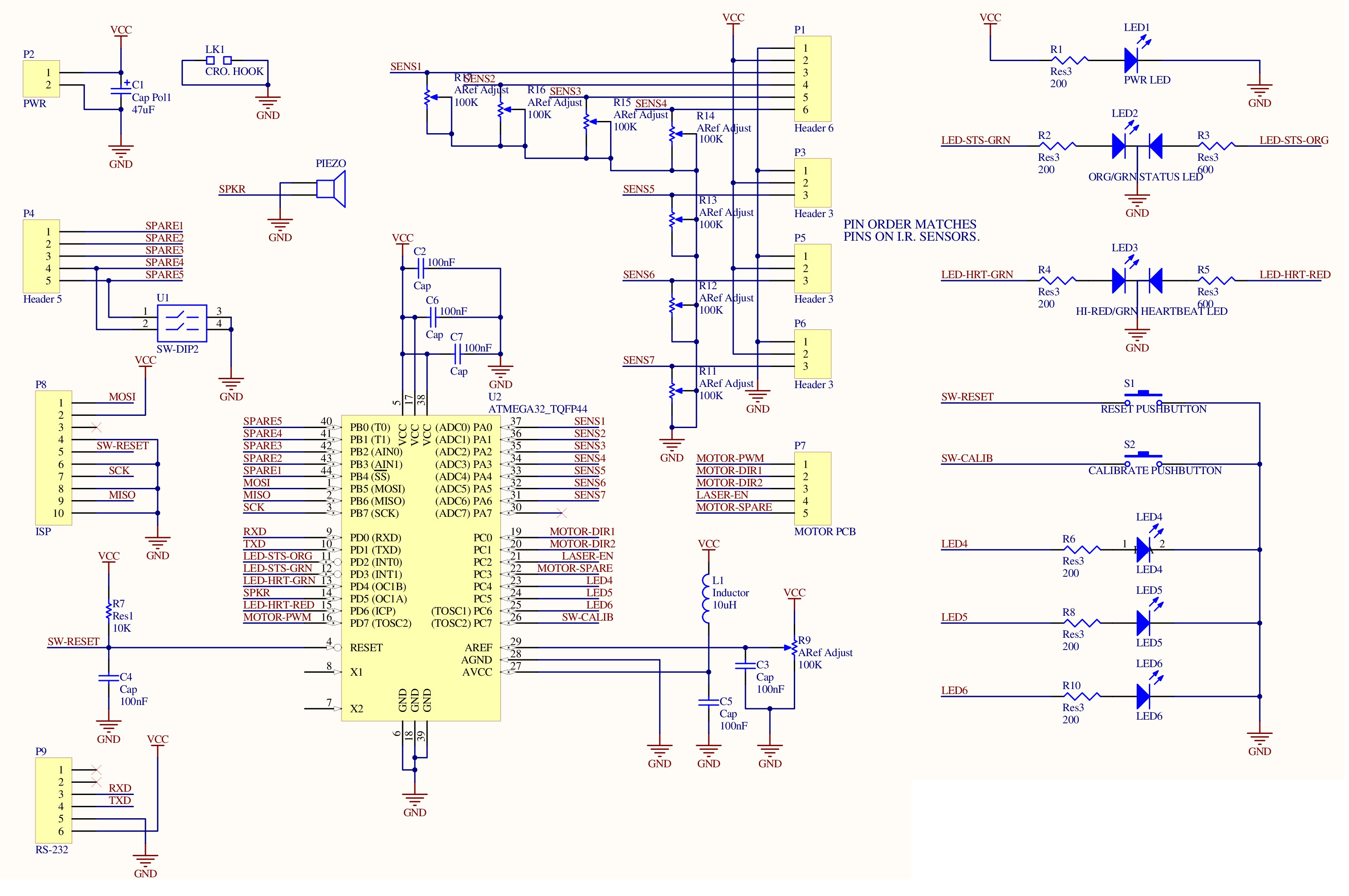
The circuits were re-drawn on the computer to produce a schematic diagram (Fig. 7) using a CAD (Computer Aided Design) software program called Altium. This allowed us to check how the electronic components could be arranged on the PCB and how much total physical volume of space would be required to tightly integrate the electronics within the mechanical design. The PCB design process is described in more detail later. High-resolution schematic diagrams for all 3 circuits are included in the design report at the end of this page.
the main circuit.
| 3. Each part was drawn on the computer to produce a 3D model using a CAD software program called SolidEdge. |
 |
|
 |
 |
|
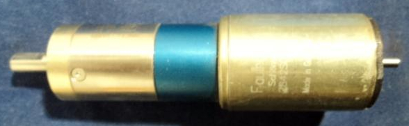
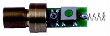
4. Some off-the-shelf components were also modeled in CAD. The motor is a Faulhaber model 2842012C, which is a 12 volt model in the 2842 series. The laser transmitter (Fig. 12) consists of a 1mW 650nm diode and driver circuit that was striped from a cheap laser pointer. The battery spring terminal was de-soldered and the pushbutton switch was replaced with a wire from the driver transistor.
 used. See the final design report for the correct specifications and a CAD drawing. |
 |
5. The parts and components were assembled together “virtually” using CAD to make a model of the final product, to ensure that everything fits together as expected. The fit between the battery module and its bracket (Fig. 13 – 14) was tested. The external dimensions of the battery module (Fig. 15) was verified to ensure that it would fit within the satellite body and that there was sufficient clearance for wires.
 of the motor. |
 |
 |
The final design for the satellite is shown below.
Note: The assembly section drawing (Fig. 16) is out-of-date and two improvements were made to the design. The reaction wheel was manufactured using a solid piece of steel, not multiple pieces of steel plate like the drawing shows. And the laser sub-assembly was simplified from 3 parts to 2 parts.
Using CAD we produced 3D renderings of the assembled satellite, which help to visualize the final product.
 |
 |
 |
 |
||
6. For each part that needs to be manufactured, a 2D mechanical drawing was produced. These drawings were used by the machine operator to manually machine the part.
Note: using the latest multi-axis CAM (Computer Aided Manufacture) machines, it is possible to produce metal or plastic parts directly from a 3D model on the computer.
Some of the 2D drawings are shown below (Fig. 21 – 26). The complete set of mechanical drawings are included in the design report, which is linked at the end of this page.
 |
 |
 |
 |
 |
 |
Manufacturing the parts
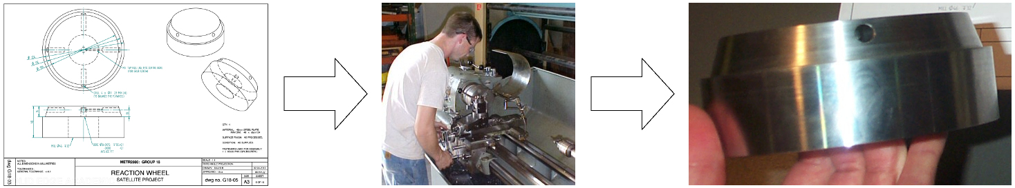
The reaction wheel was machined from a block of steel using a milling machine, and finished in a lathe. The machinist needs to read the mechanical drawing, interpret the specifications of the part and plan a sequence of steps to manually operate the mill (Fig. 27).
The other parts were produced from nylon plastic using a rapid-prototype printer. The SLS (Solid Laser Sintering) method uses a laser to deposit small pieces of molten nylon plastic. The part is built-up in thin layers to produce the final part.
To build over-hanging features and holes, the printer deposits a special, soluble scaffolding material which gets washed away when the job is complete. The components come out of the printer ready-to-use, with only a light sanding required.
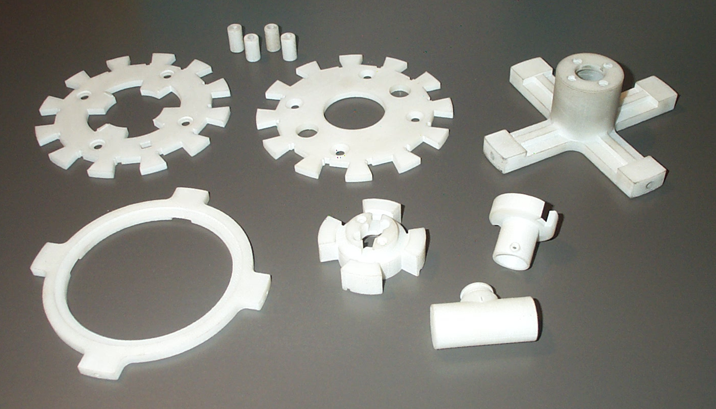
Note: the material is quite porous and some of the parts are
discolored because they were handled with dirty fingers.
Assembling the Prototype
A prototype of the satellite was built to validate the mechanical and electronic design. It also allowed us to start developing the software for the microcontroller.
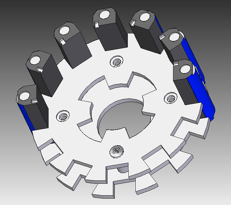
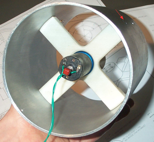
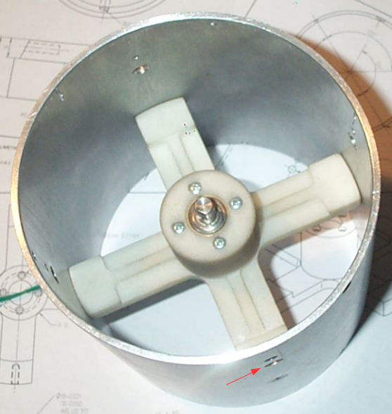
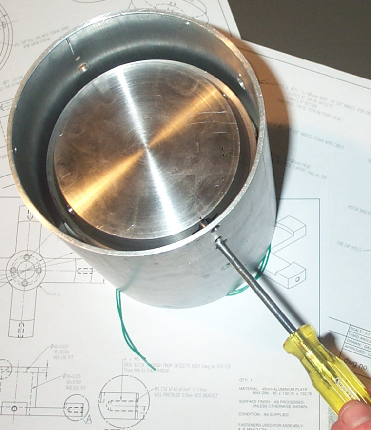
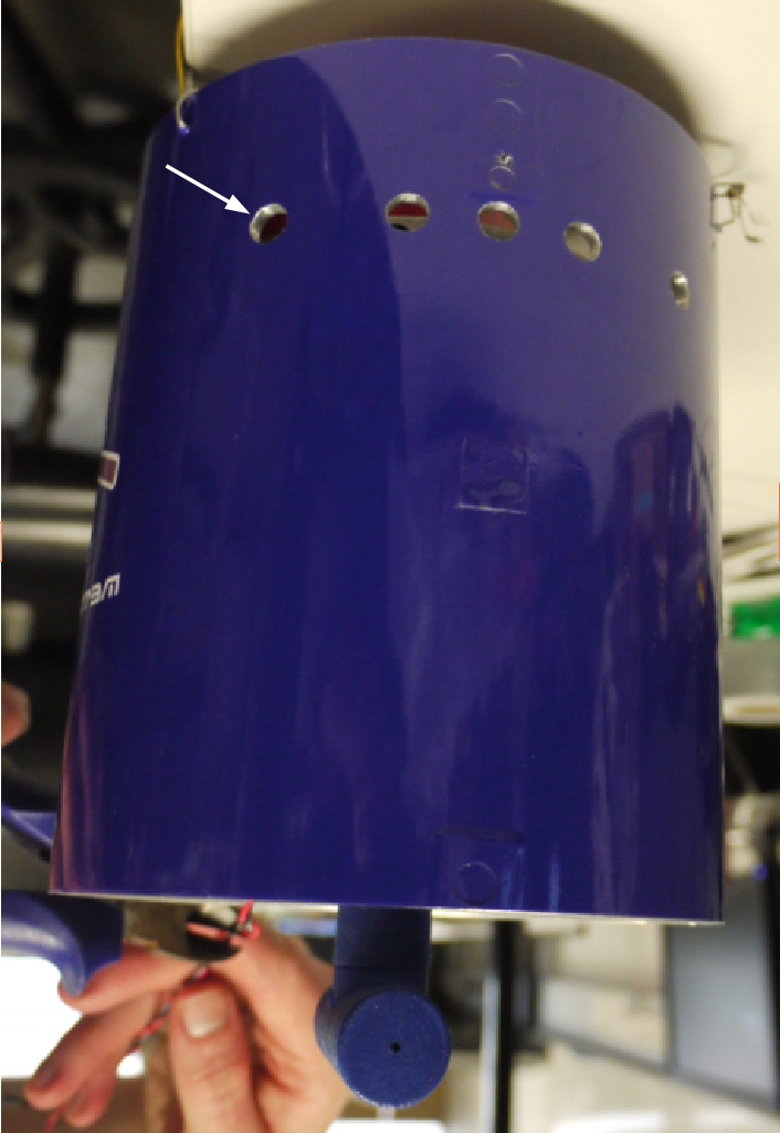
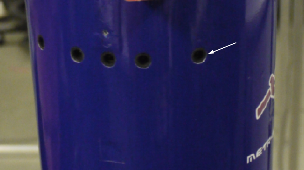
The body of the satellite is an aluminum tube. Various holes were required to attach the motor support bracket, the PCB bracket, the I.R. sensors and the support wires. These were drilled and countersunk using a drill-press.
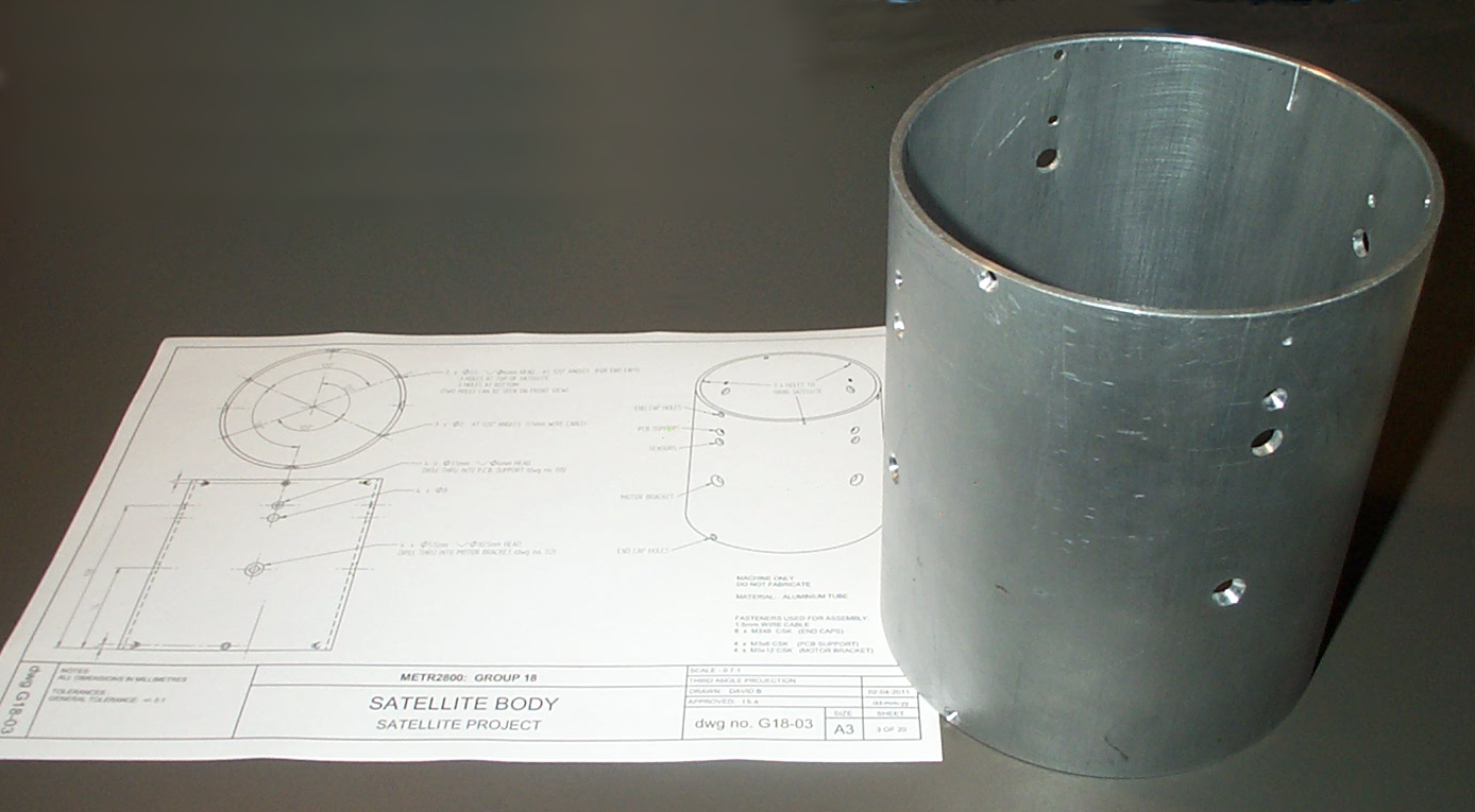
and the finished aluminum tube.
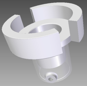
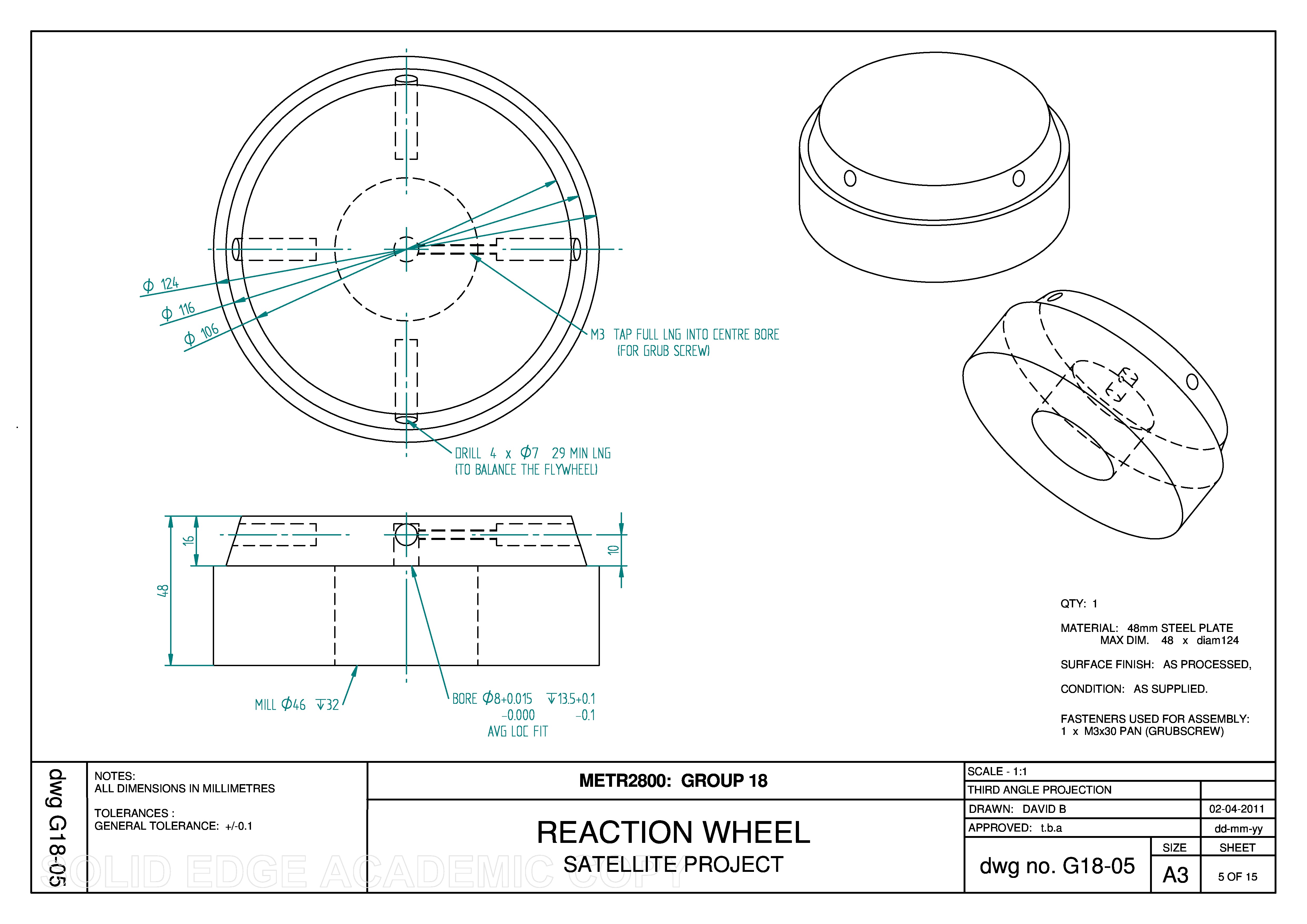
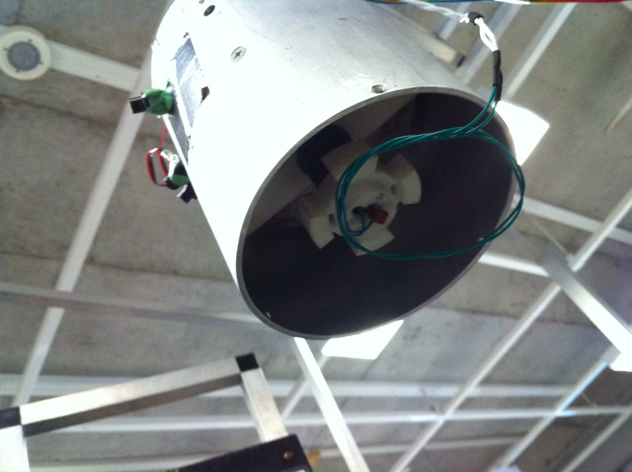
The reaction wheel is made of steel and weighs 6 kg. When the the motor applies a torque, this heavy mass actually remains almost stationary and the satellite spins around the reaction wheel. The reaction wheel has one threaded hole to attach it to the flat face of the motor shaft. Another 3 holes were added to balance the inertia. The chamfer provides clearance for the I.R. sensors that are attached to the inside of the satellite body.
and the final part.
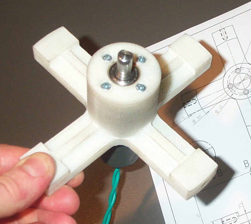
| The motor support bracket was 3D printed in nylon plastic. The motor/gearbox fits into the bracket with a “location” fit, although the tolerance of the printed part is not very accurate. Four 3mm round-head bolts go through the bracket and screw into the motor (Fig. 31).
Each arm of the support was printed with a hole that was tapped by hand with a 5mm thread (Fig. 32). Wires were soldered to the brushed DC motor along with a noise-filtering capacitor. |
 |
 |
|
 |
The reaction wheel is attached to the motor using a 3mm grub screw that is tightened so it hits the flat side of the motor shaft. |
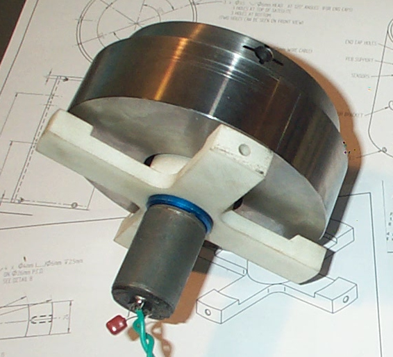 |
The motor bracket is attached to the satellite body using 4 x 5mm countersunk bolts (See red arrows in Fig. 35 – 36). It was actually easiest to assemble the motor and reaction wheel together first (Fig. 34) and the install them in the satellite.
 |
 |
 |
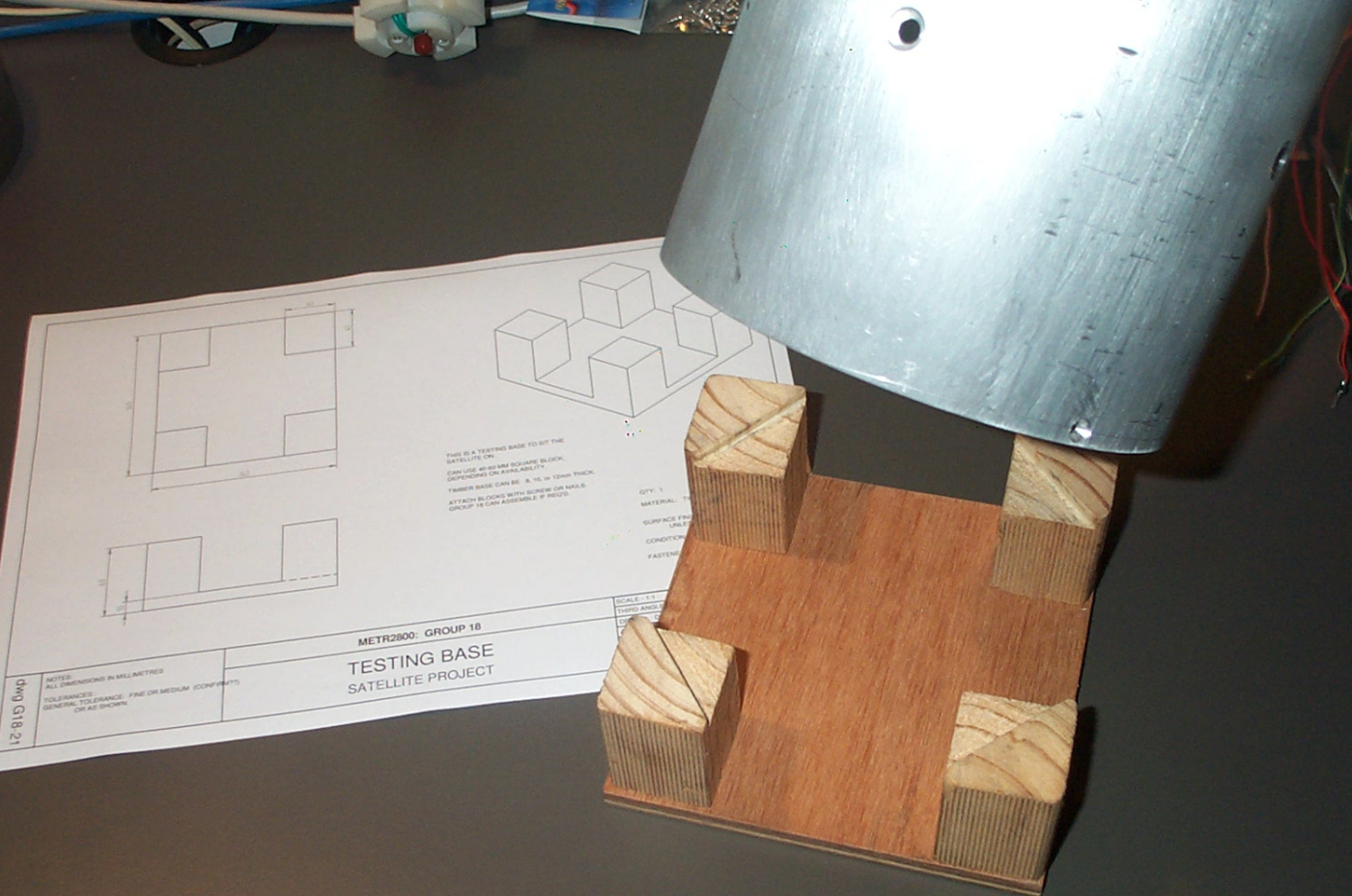
| The laser will hang down underneath the satellite which makes it hard to work with unit on a flat surface. Therefore a special base was made to support the satellite whilst sitting it on a work bench. |
 |
Software Development
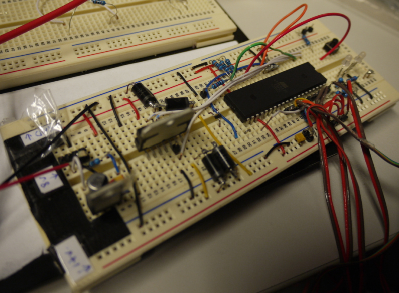
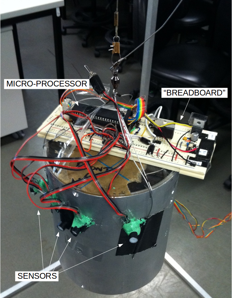
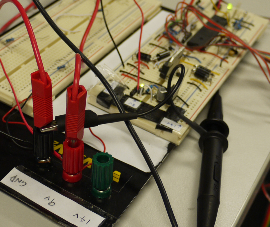
The electronic circuits were assembled on a breadboard so that we could start programming the microcontroller. This meant we could work in parallel, doing both software development and manufacturing the final PCBs (Printed Circuit Boards).
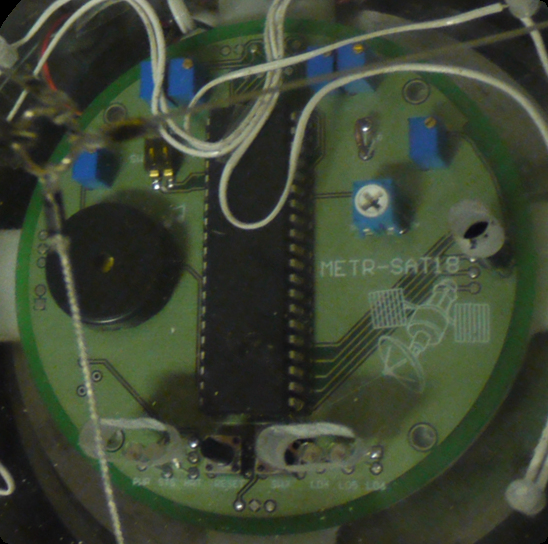
When building a breadboard it is typical to use through-hole components that can be pushed into the spring-loaded holes. Instead, we used the same surface mount components as would be used on the final PCB. This takes longer to build but it reduces potential problems caused by later substitution of parts. On the breadboard (Fig. 39) you can see the 5 volt regulator with the metal fin (left side), the motor H-bridge controller with a larger metal fin, and the big 40-pin chip is the Atmel ATmega32 microcontroller (right).
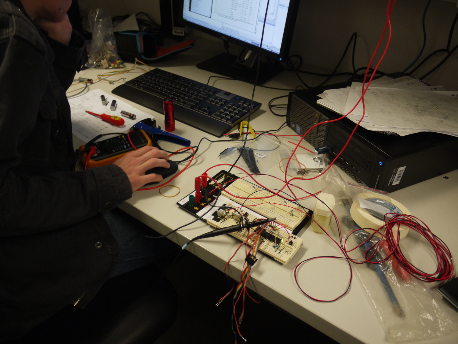
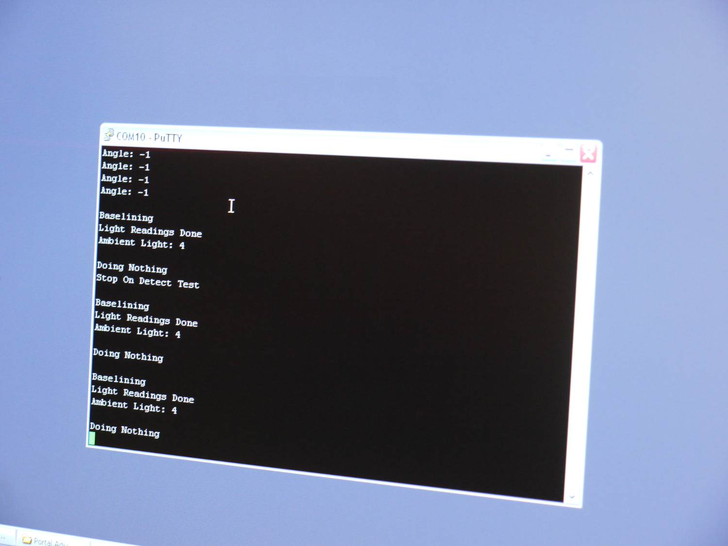
The device is connected via temporary cables to a desktop computer (Fig. 40). One cable called an ISP (In System Programmer) is used to download the software to the Satellite in assembly code. A second cable is a bi-directional RS-232 connection that allows us to give commands to the satellite via the keyboard or view diagnostic information in a terminal window (Fig. 41).
 |
 |
 |
Testing the prototype
| We conducted initial testing of the satellite using a prototype that was partially assembled with the help of some adhesive putty (“Blu-tack”) and gaffa tape (Fig. 42).
The location of the 5 I.R. (Infra-Red) sensors was designed so that they had overlapping fields of view. We experimented with the sensor’s positions (with respect to the rotation axis) but ultimately our original design decision was suitable. A bigger impact was found by experimenting with shrouds placed over the sensors to shield excess I.R. or visible light. We tried long plastic tubes (Fig. 42) that provided a highly directional response to I.R. light. However we found that the system worked best when each sensor has an almost linear response as the satellite rotates towards the I.R. light source. In the final product the I.R. sensors were mounted with almost no shrouding (Fig. 80 – 81) and the light response was tuned using individual variable resistors on the PCB. |
 |
 |
PCB Production
The process of designing the circuits to manufacturing the PCBs (Printed Circuit Boards) is outlined below:
| 1. Design on paper. The required circuits are designed and sketched on paper. More complex circuits can be simulated using computer software. |
|
 |
2. Build a prototype. To test the circuit design, electronic components are pushed into a “breadboard” to create a temporary circuit. |
| 3. Re-draw circuit schematics on computer. |
 |
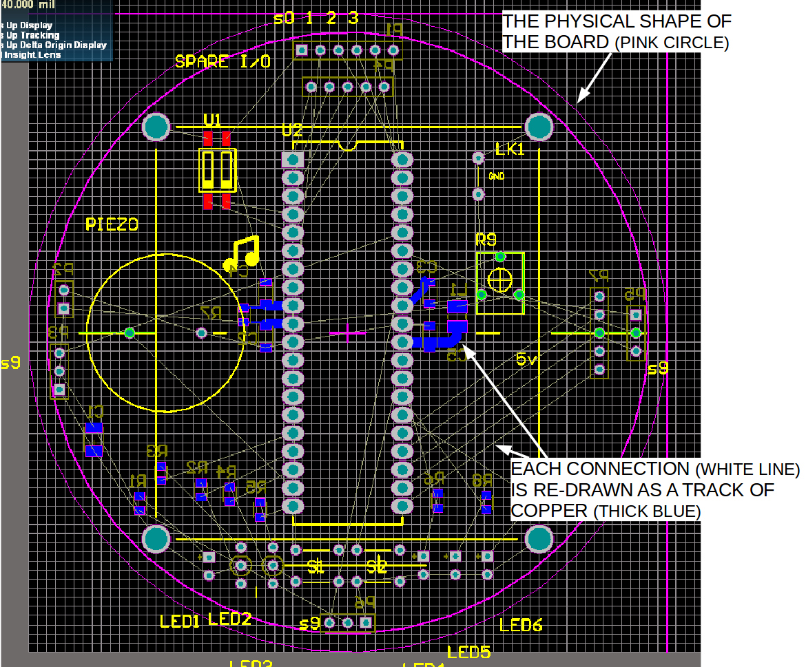 |
4. Convert schematic to circuit board design. Each component is placed on a model of the physical board to determine their optimal position. Components can be moved to either face of the board and the component pins are interconnected using lines (the thin white lines shown in the image left). This “rats nest” of connections leads to the next step #5. |
| 5. Draw the PCB (Printed Circuit Board). The tracks of conductive copper on each layer are drawn by hand. Each connection between the pins of two components is re-drawn as a “track” (shown in red). The goal is to route all the copper tracks without any overlaps. Sometimes the process of steps 4 and 5 is iterative because moving a component might result in a more simple design for the PCB tracks. It is also possible to connect a track between layers using a vertical tube of copper called a “via”. |
 |
 |
6. Manufacture PCB. A photographic and chemical process converts the image of each layer of copper into tracks of conductive copper on a panel of insulating material e.g. fibreglass. A “solder mask” layer is printed on top of each layer of copper that acts both as an insulator and makes it easier to solder components. Lastly, a “silk screen” ink layer is printed on the two external faces that includes product information and markings to help place components. |
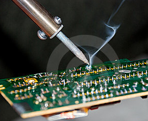
| 7. Install electronic components on PCB. Both through-hole and surface-mount components are assembled by hand soldering. If a PCB has a large number of surface-mount components, you could potentially do re-flow soldering with an oven. And if you are manufacturing a large quantity of PCBs you could use an SMT assembly machine. |
 |
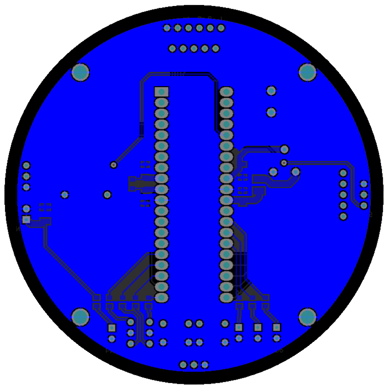
Final PCB Designs
All the circuits were simple enough that we could use double-sided 2 layer PCBs.
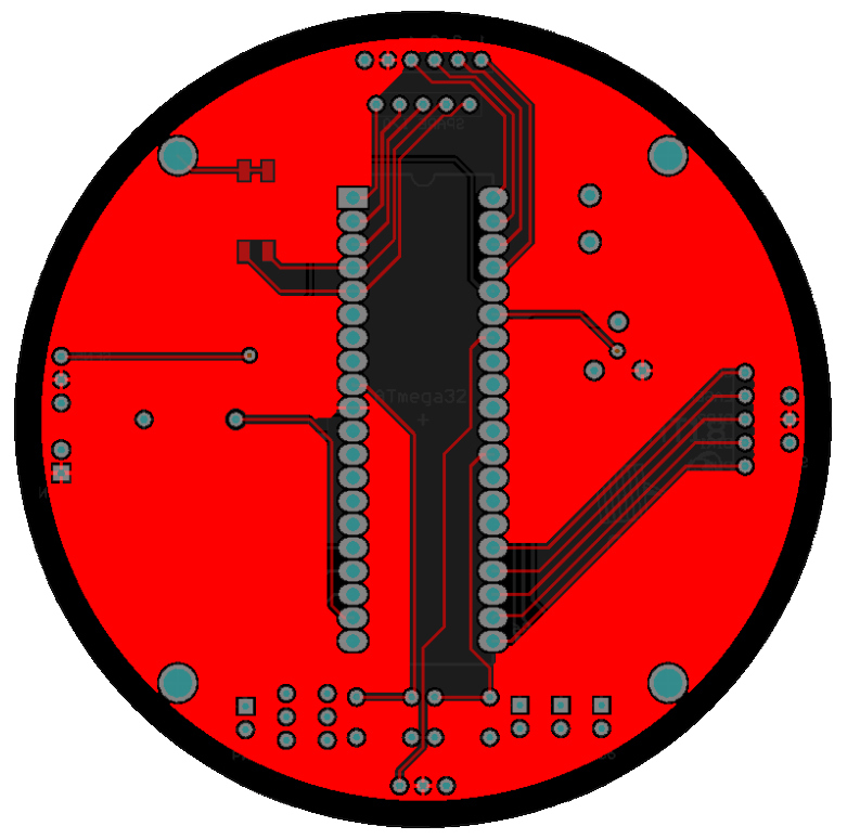
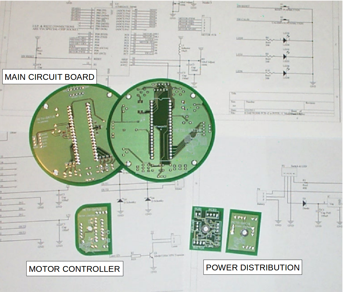
The mainboard was designed to be a circular shape to match the satellite body. The PCB would be visible through the clear plastic top cap at the top of the satellite so we gave some consideration to its aesthetic appearance. The “art” of PCB design is a trade-off between making switches and connectors easily accessible, aligning components so they have a professional-looking symmetrical appearance, making the “rats nest” of interconnections simple enough that you don’t need to add too many vias or layers, and not introducing electrical side-effects like noise or RF radiation.
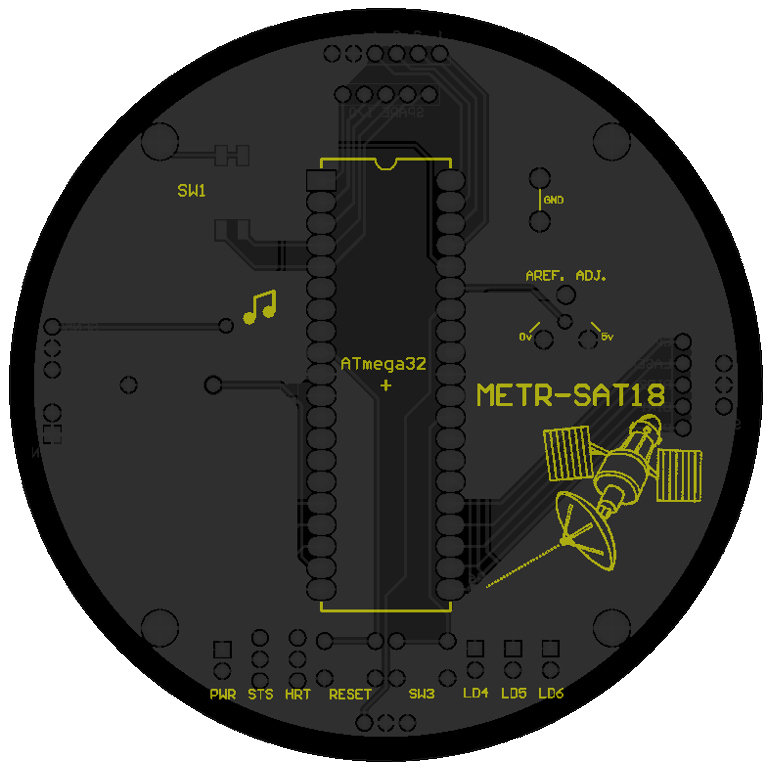
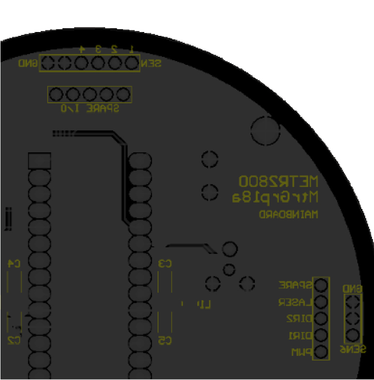
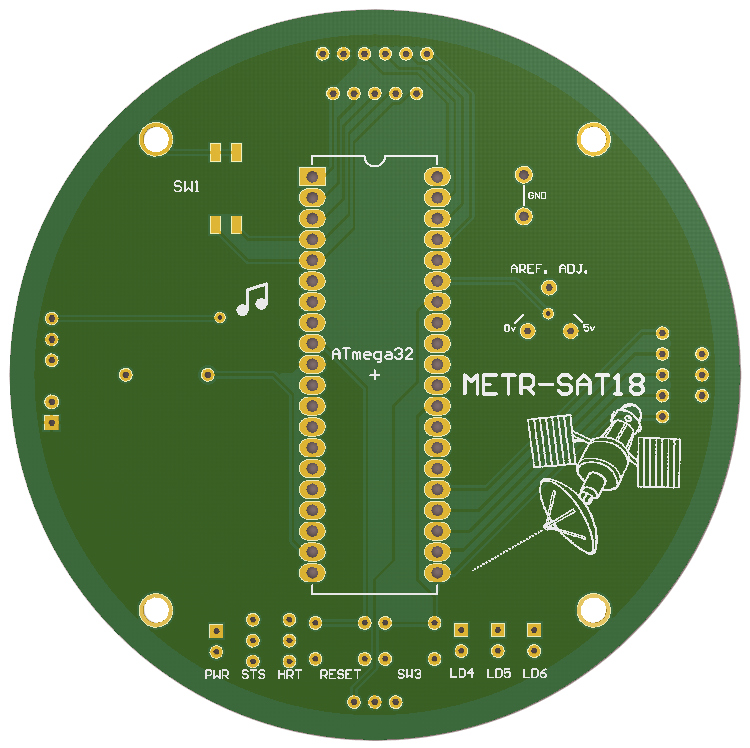
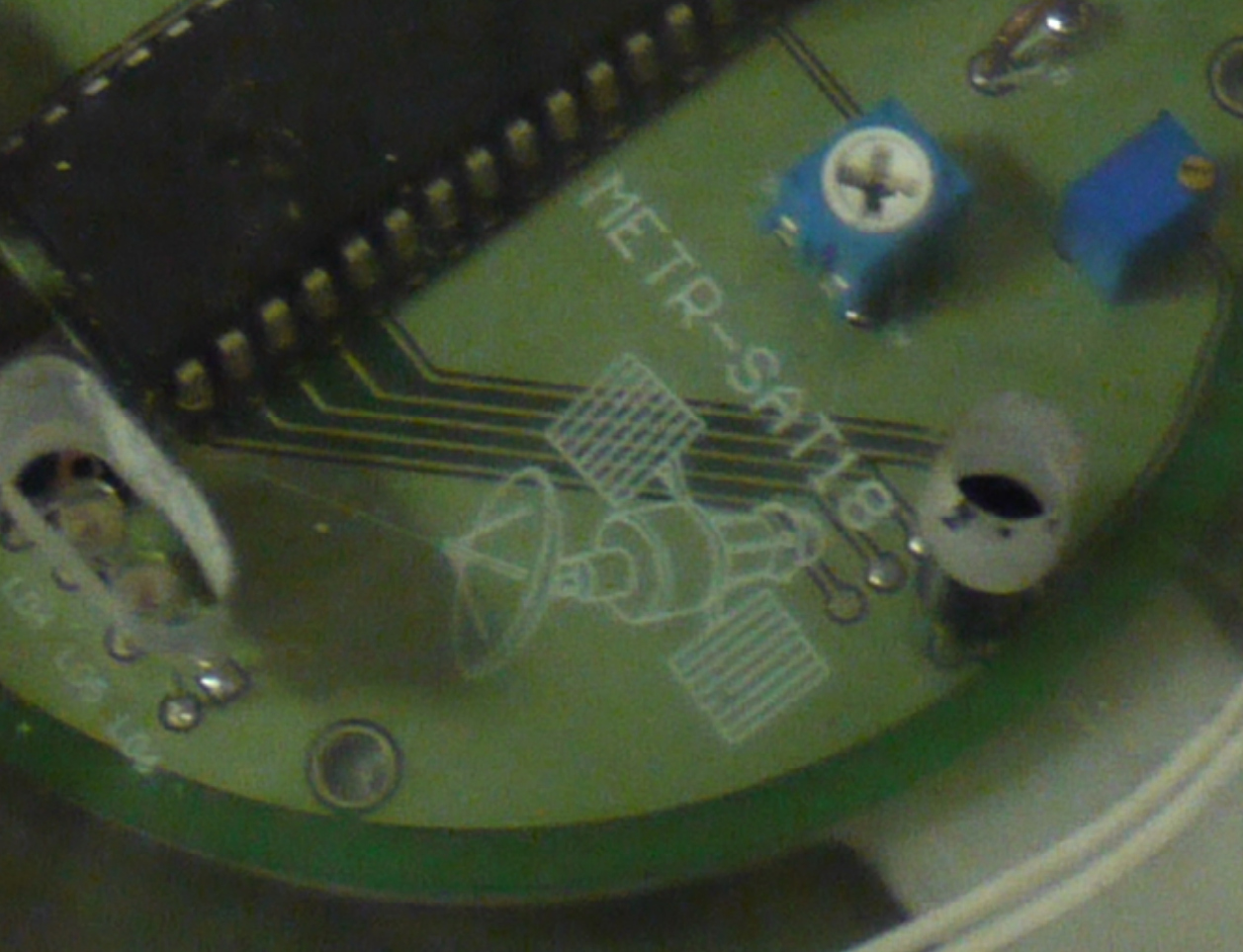
The size of the board was made just big enough to accommodate the required components. There are 4 holes to screw the PCB onto its support bracket. There are 6 LEDs to display the satellite’s operational status and a piezo buzzer for fun (Fig. 45 – 46).
Note: These drawings are out-of-date and the PCB used in the final product had 6 variable resistors (“trimpots”) used to calibrate the I.R. sensors, of which 5 were actually used.
|
|
|
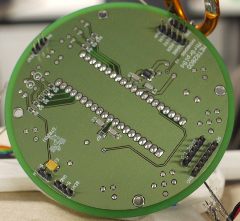
The top layer of the mainboard (Fig. 47) includes a +5 volt plane that will be insulated by the solder mask layer. Square or rectangle-shaped pads are used to indicate the positive leg or first pin of a through-hole component. In the top-left are the rectangular pads for a surface-mount 2-pole DIP switch that will be soldered on the top face of the board. The top silk-screen layer (Fig. 48) has various text including labels for the LEDs: “PWR” = power, “STS” = operational status, “HRT” = microcontroller heartbeat.
The bottom layer (Fig. 49) includes a ground plane. There are lots of rectangle-shaped pads to solder surface-mount components on the underside of the board. The bottom silk-screen layer (Fig. 50) includes ID numbers for the surface-mount components and external connectors.
 |
 |
 |
 |
The Altium PCB design software can produce renderings showing what the PCB will look like when the copper layers, solder mask and silk screen are applied together (Fig. 51 – 52). It’s also possible to add 3D models of each individual component, however for this project we modeled the mainboard as a disk-shaped volume where the maximum height is that of the Atmel microcontroller fitted in an IC socket.
 |
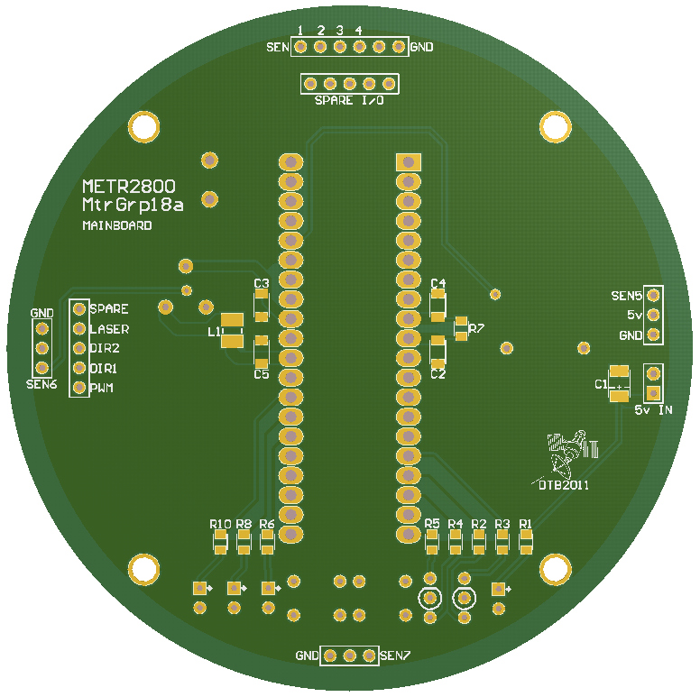 |
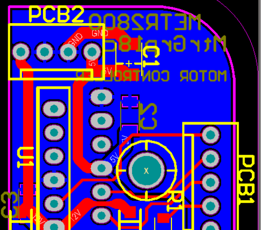
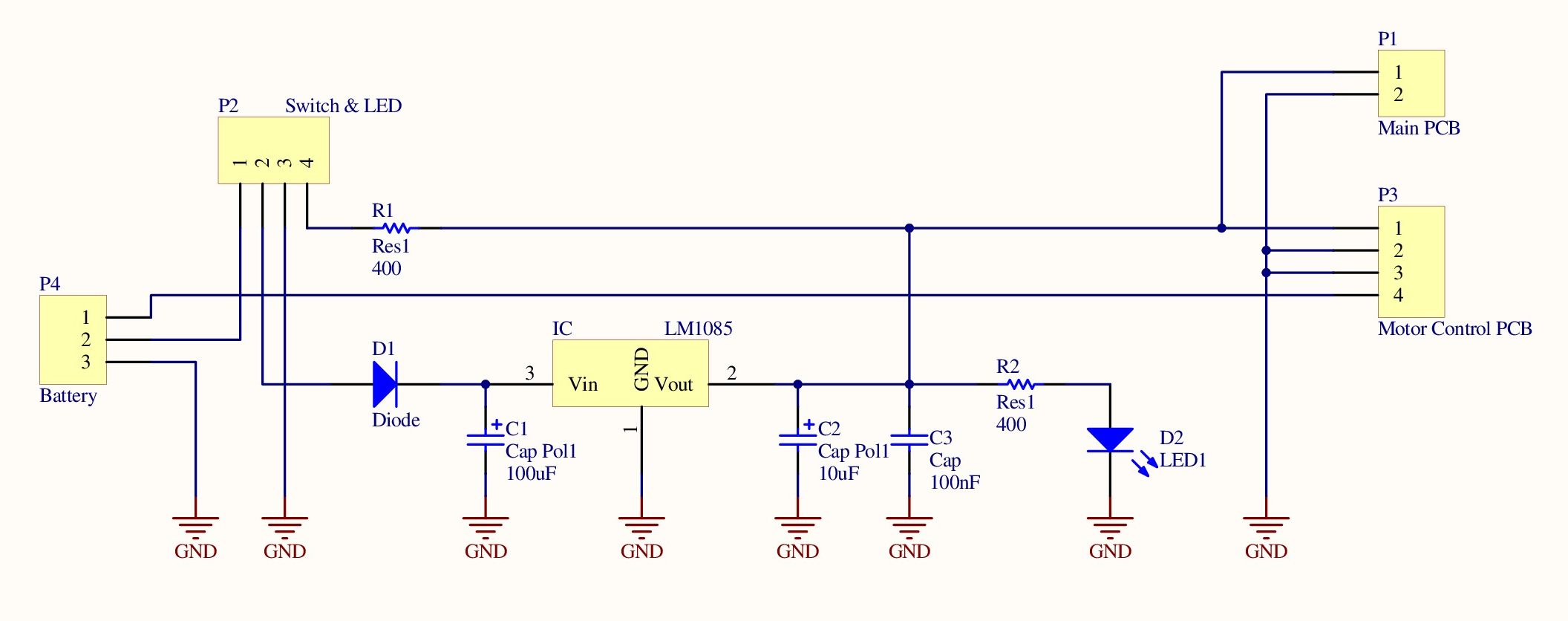
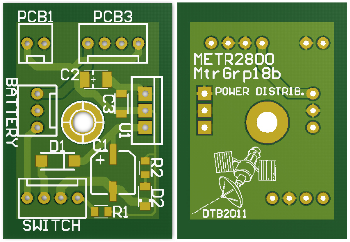
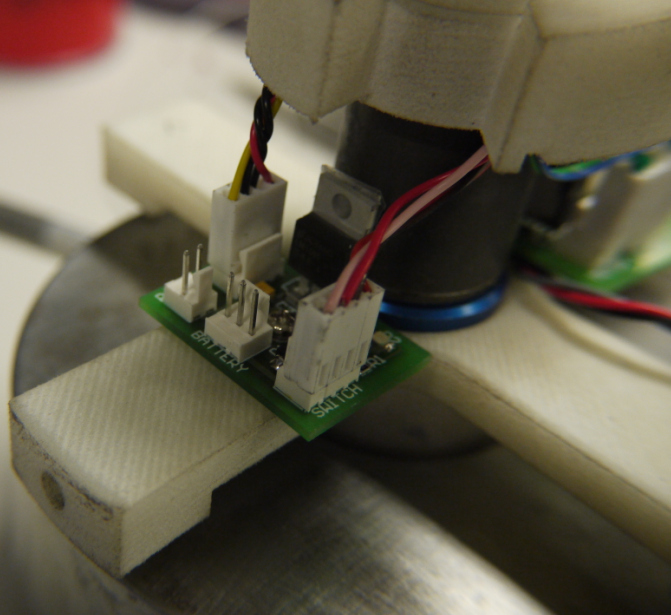
The power distribution board is located in the center of the satellite, screwed to one arm of the motor support bracket. The circuit incorporates an LM1085 5 volt regulator chip, a reverse-current protection diode, a power status LED and some decoupling capacitors (Fig. 53).
 |
 |
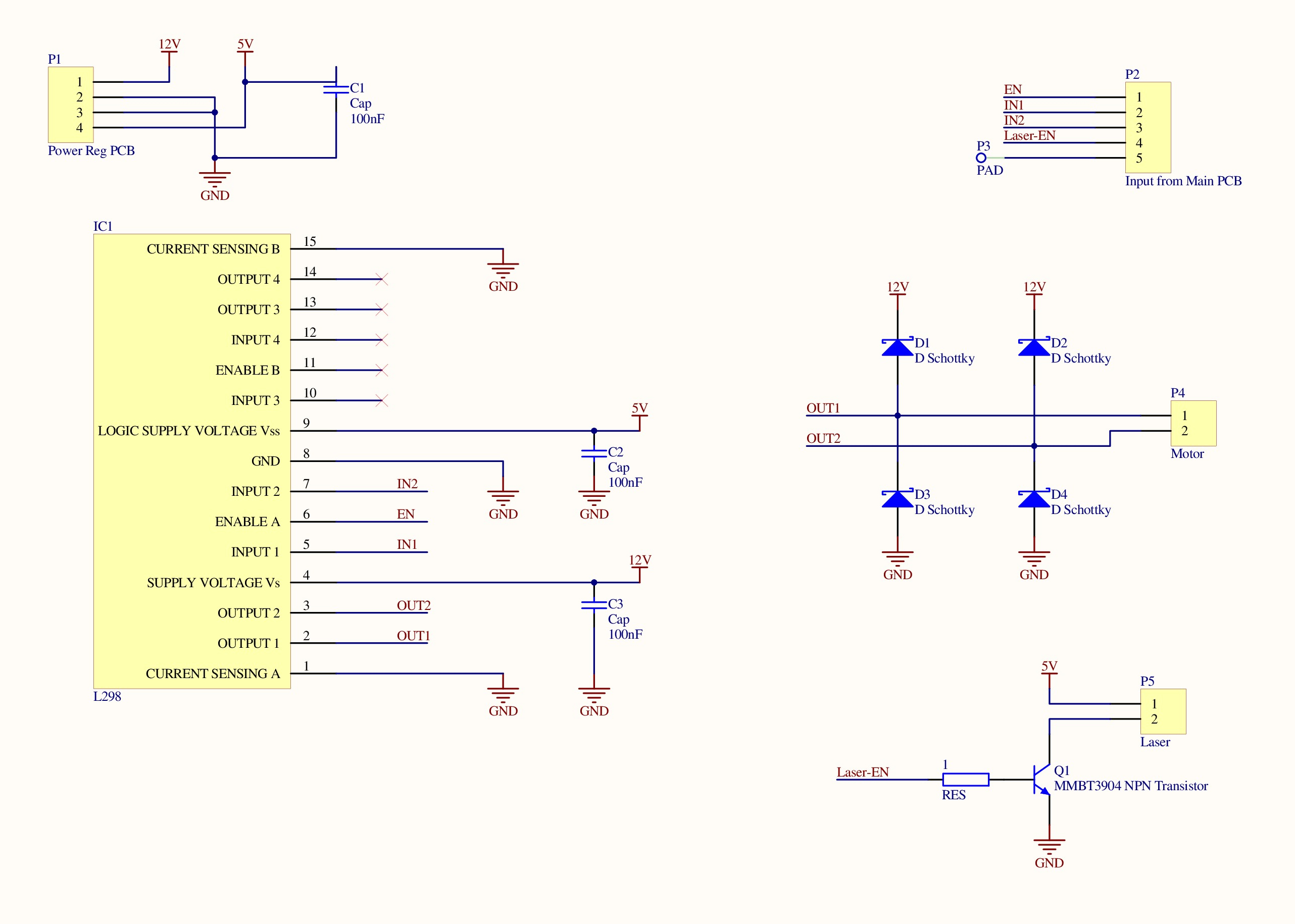
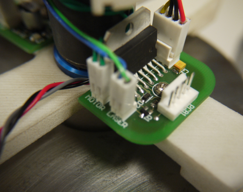
The motor controller board is also located in the center of the satellite. The circuit uses a L298 H-bridge chip, 4 schottky fast diodes and some filtering capacitors (Fig. 55). An MMBT3904 transistor is used to switch the laser transmitter module.
 |
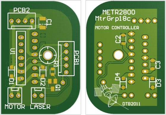 |
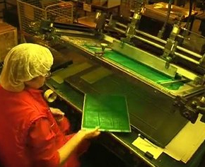
When manufacturing the PCBs we ended up with some duplicate boards (Fig. 57). Circuit boards are produced in batches, on “panels” of fibreglass material. The total area of the 3 PCBs was less than the smallest size “panel” offered by the manufacturer, therefore they used some of the excess panel by adding extra copies of the artwork.
The green-colored “solder mask” layer makes the copper tracks appear to be light-green whilst the underlying fibreglass board appears to be dark-green. A “paste mask” layer was added by the factory to coat the copper pads with a thin silver-colored layer of solder tin. This prevents oxidization of the bare copper and makes it faster to solder components.
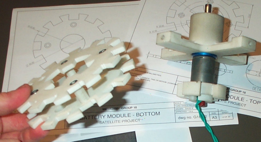
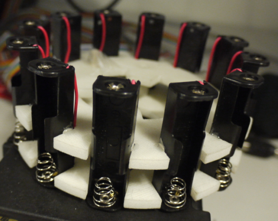
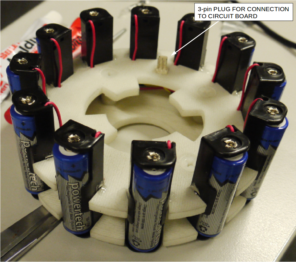
Assembling the Battery Module
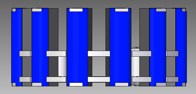
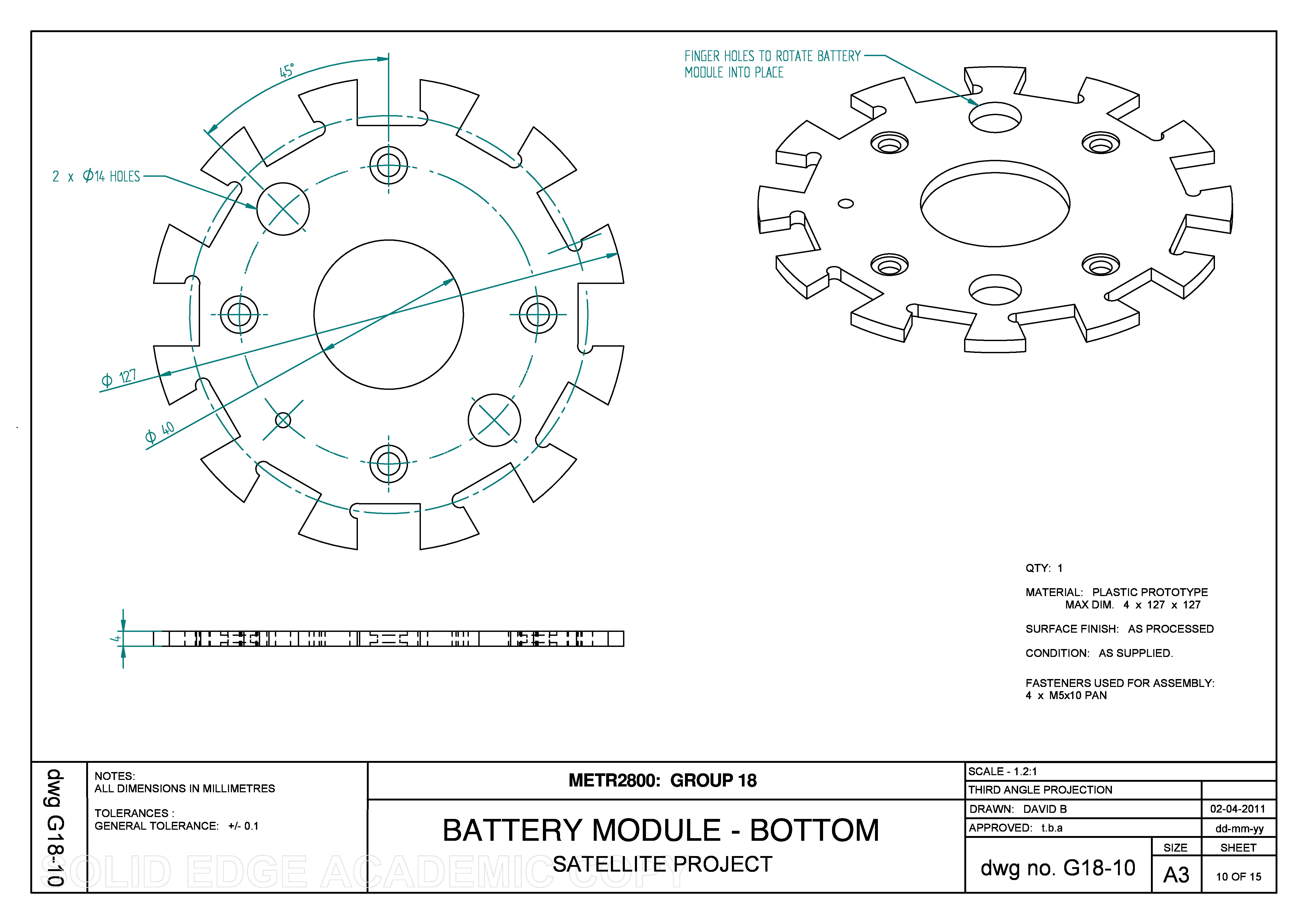
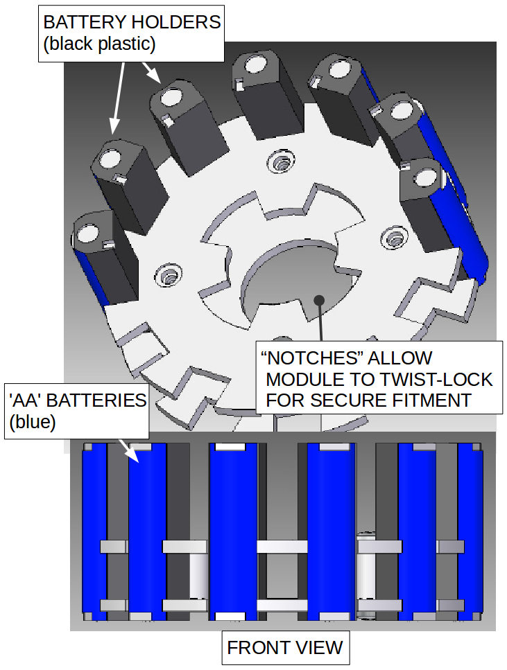
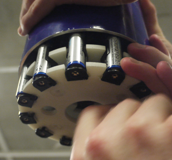
| The battery module has 12 x ‘AA’ size batteries. This battery size was chosen because they can be physically arranged to distribute the mass, in contrast to larger batteries that are shaped like blocks. Also ‘AA’ batteries are available in both standard alkaline or rechargeable types.
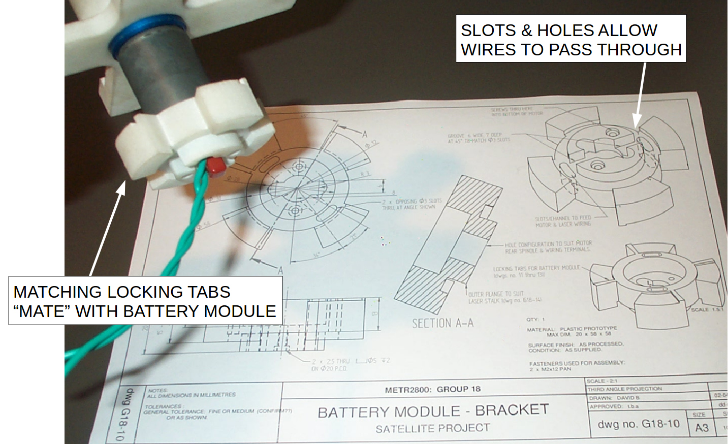
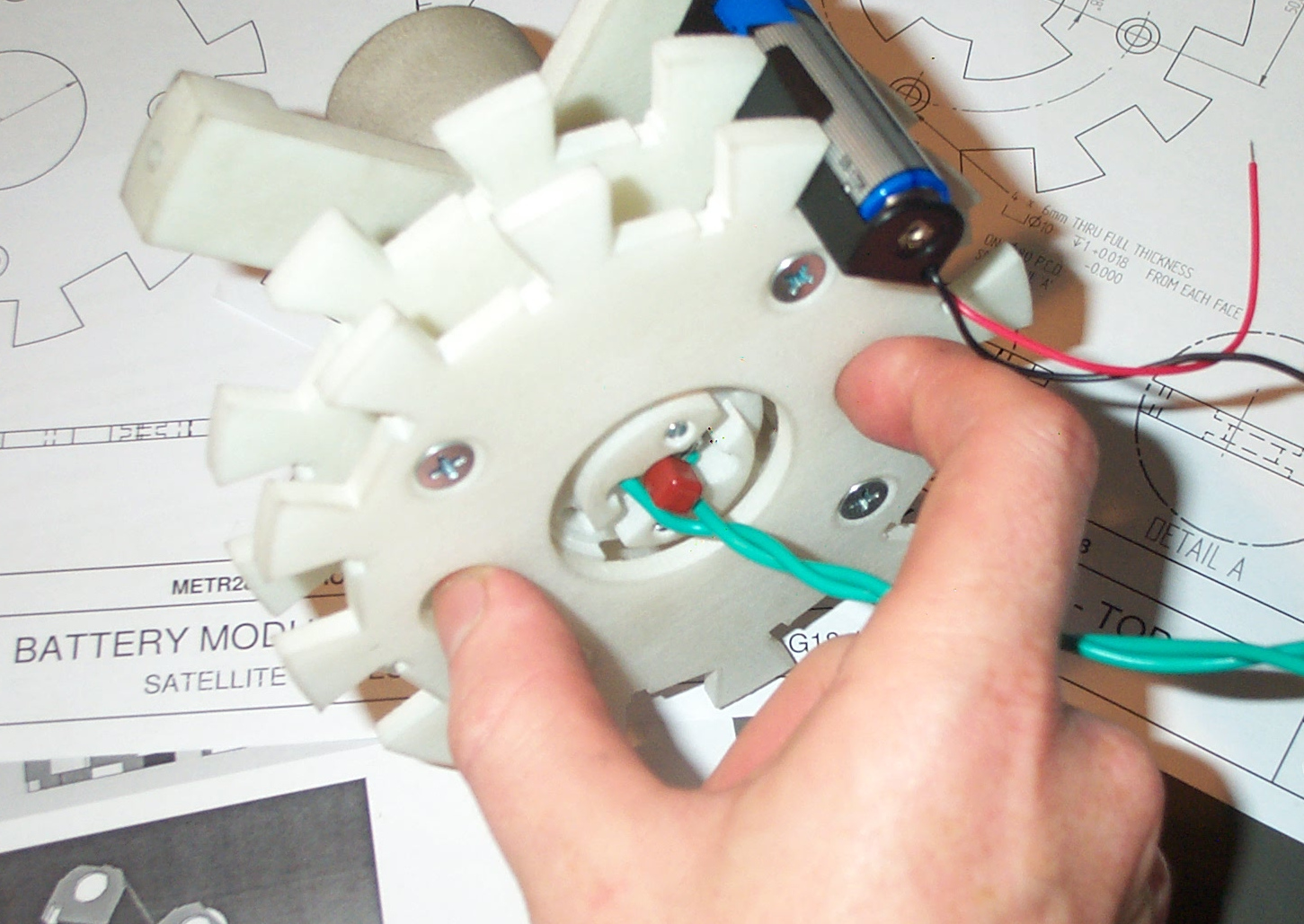
We used 1.4 volt NiMH (Nickel-Metal Hydride) batteries so that whilst the satellite was being tested, a second set of batteries could be recharged on the bench. Using 12 NiMH batteries, the battery module supplies 18 volts to the motor and a second 9 volt tap powers the electronics (via 5v regulator). All the parts for the battery module were 3D printed in nylon plastic. The bracket for the battery module fits over the bottom-end of motor with a “sliding” fit (Fig. 59). It’s held in place using 2 x M2 screws. |
 |
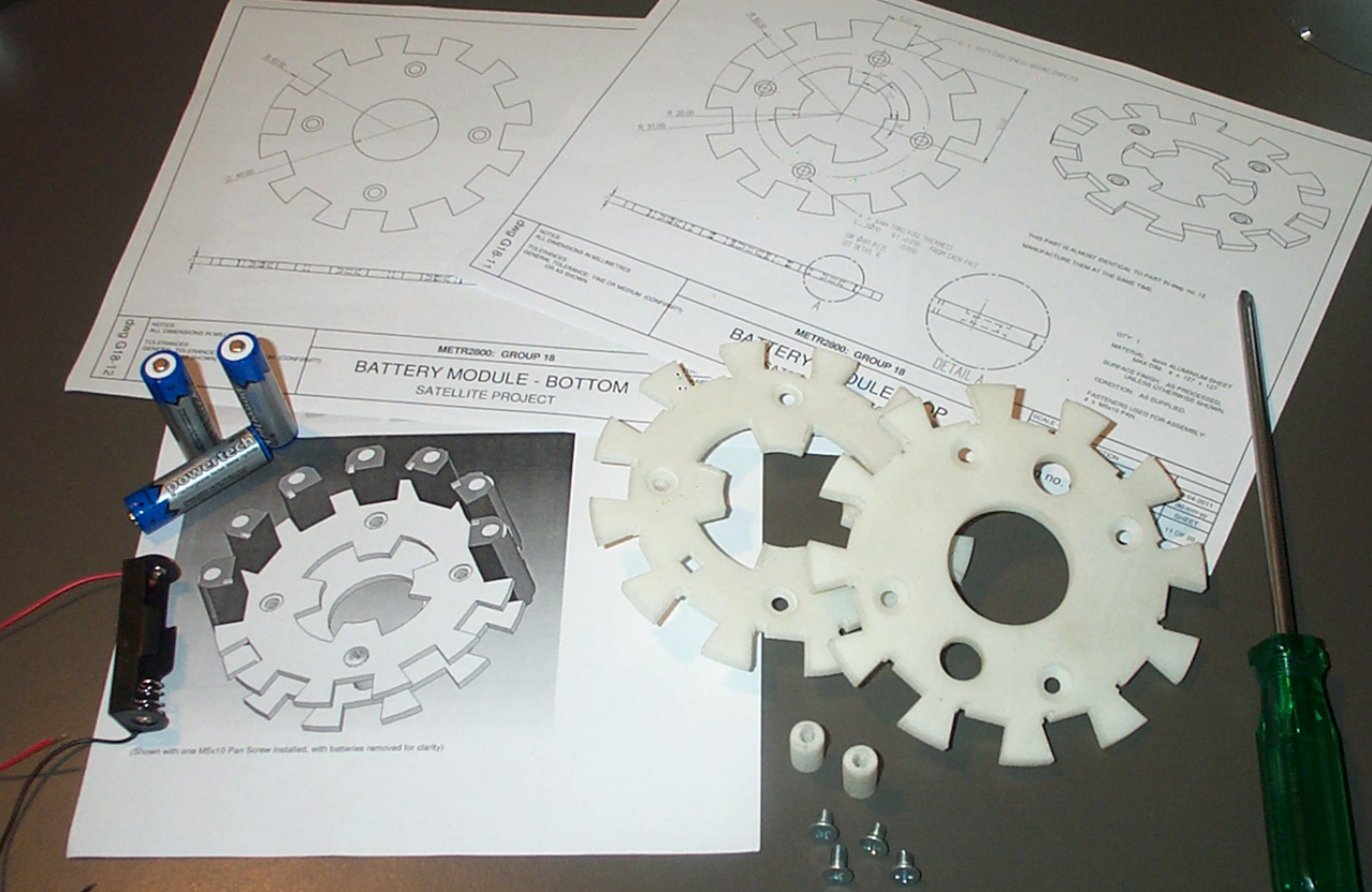
The battery module consists of two plates and 4 rods (Fig. 60). The rods were printed with through-holes and later tapped with an M5 full-length thread. The rods are sandwiched by the two plates and held in place via M5 countersunk screws. The end of each rod is recessed 1mm into the plate with a “location” fit.
 |
 |
 |
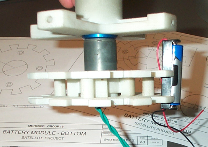
The top and bottom plates were assembled to make the frame of the battery module (Fig. 61). The clearance between the ‘AA’ batteries and the other parts was double-checked (Fig. 62). |
 |
|
| The two plates were sandwiched together using 8 x plastic M5 countersunk screws (Fig. 65). The ‘AA’ battery holders were wired together in series and affixed using a 2-part epoxy-based adhesive (Fig. 64). |
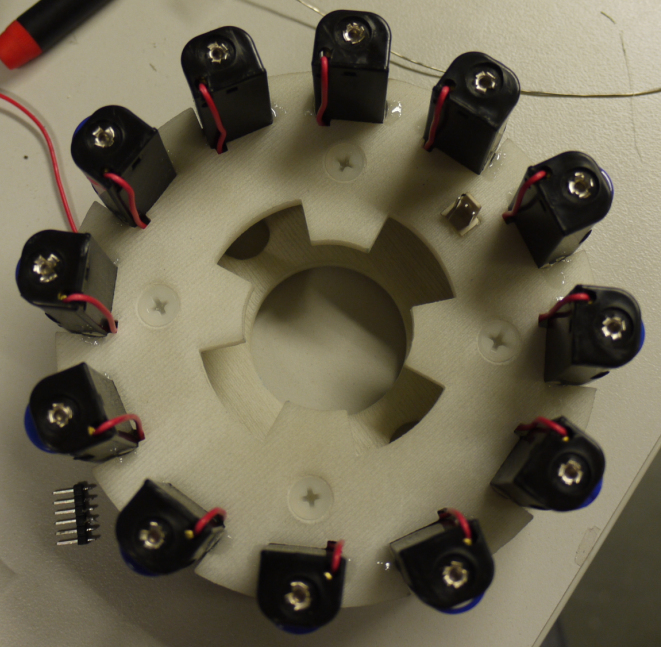 |
 ‘AA’ battery holders. |
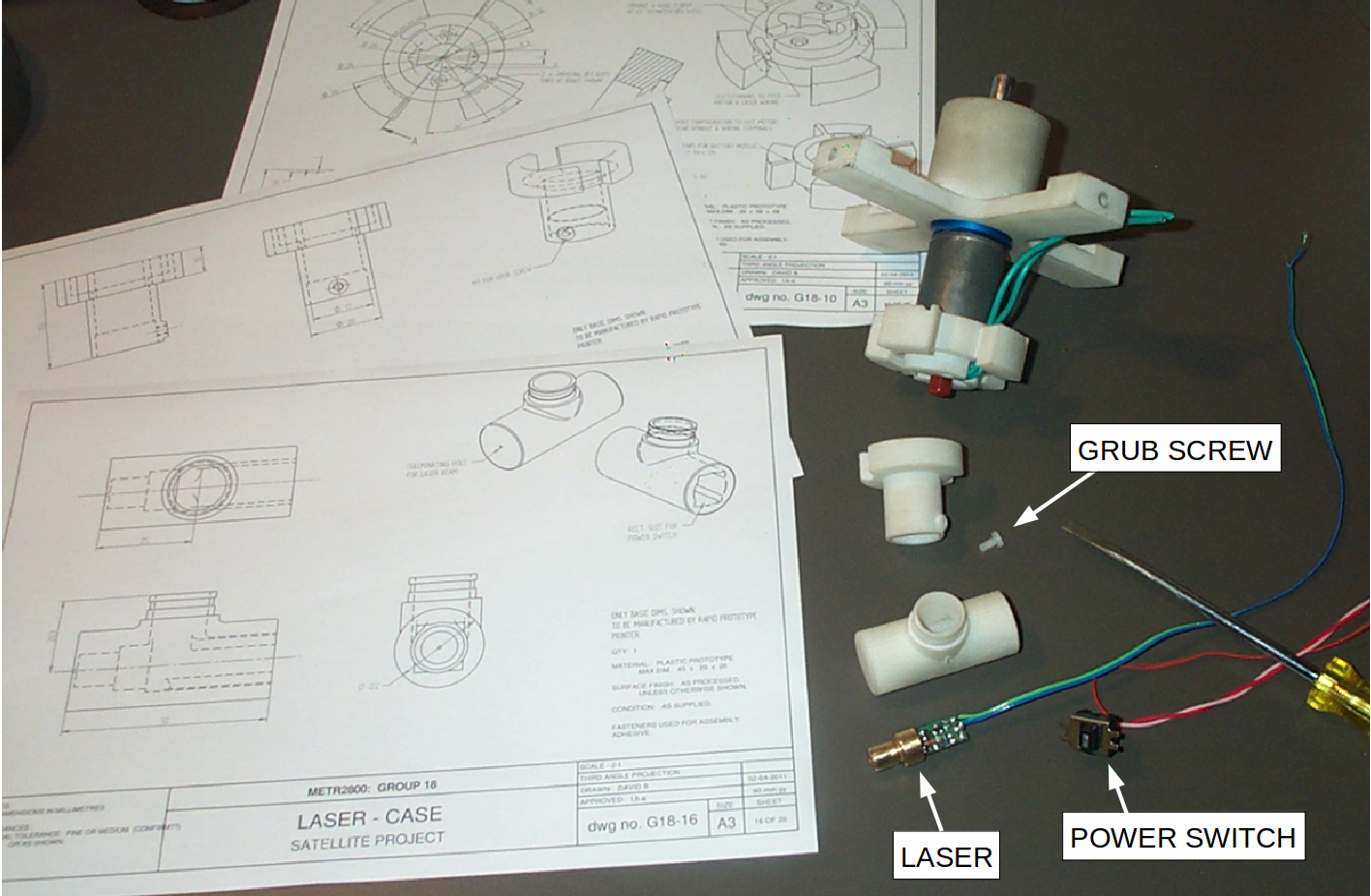
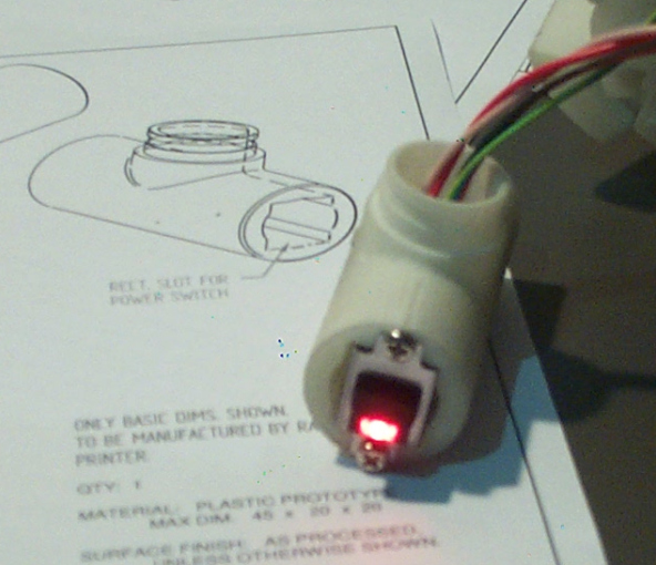
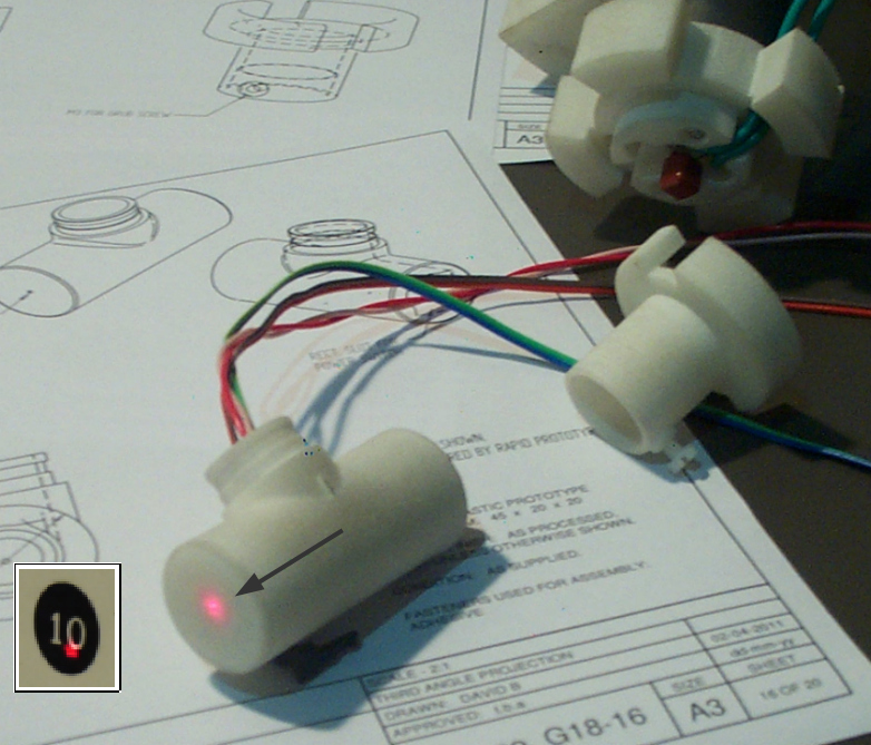
Laser sub-assembly
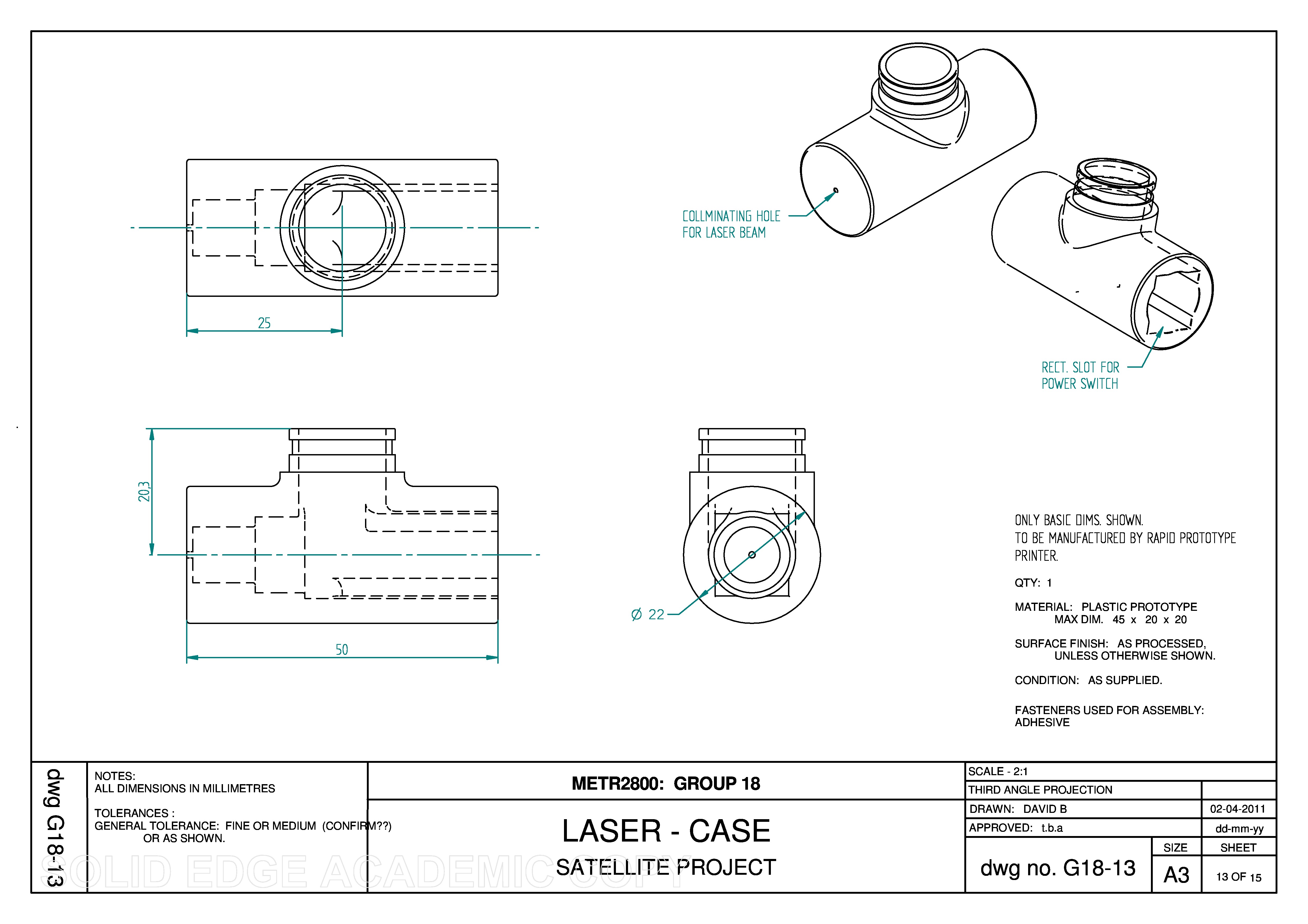
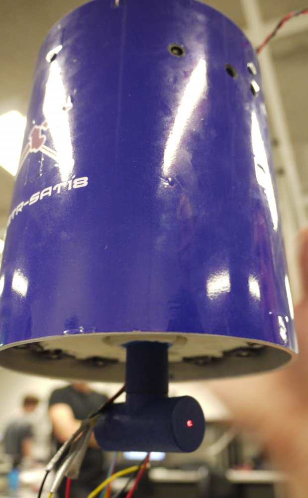
| All the parts for the laser sub-assembly were 3D printed in nylon plastic (Fig. 67). The case is fitted to the stalk with a press fit. An M3 thread was tapped in the stalk for a plastic grub screw.
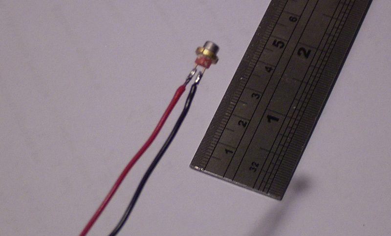
The actual laser is a module that was salvaged from a low-cost laser pointer. It consists of a red-colored laser diode transmitter and a driver circuit. The laser module slides into the case with a press fit (Fig. 68). At the rear end of the case is a sliding switch (Fig. 69) that is the master power switch for the satellite. When powered-on the switch glows red. |
 |
 |
 |
 |
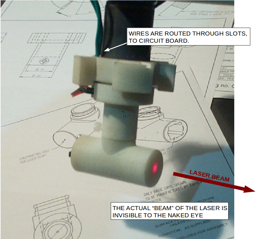 |
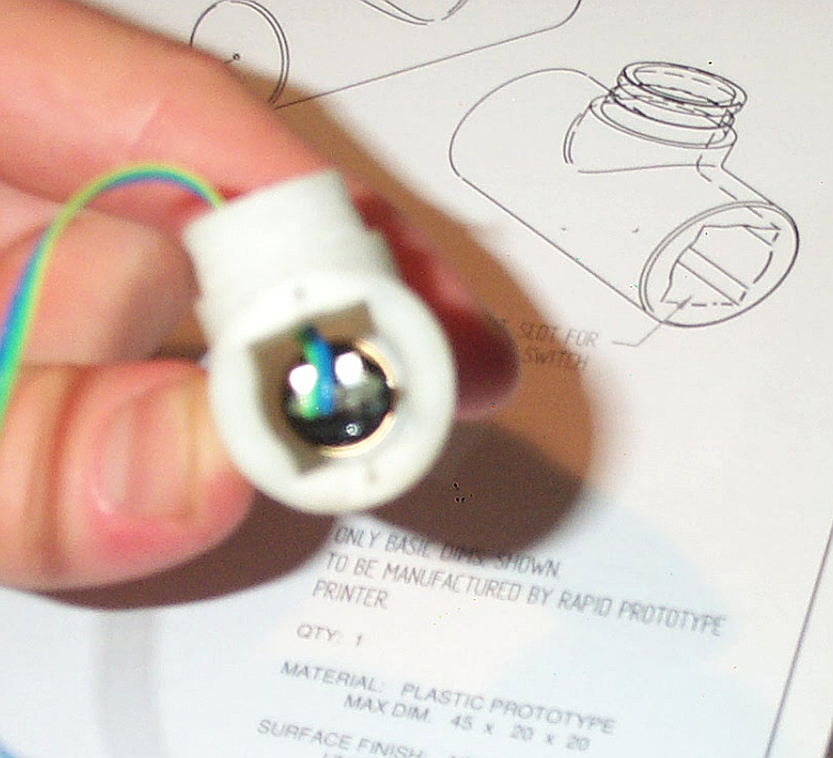
At the forward end of the case is a tiny “pin prick” hole that acts as a collminator for the laser beam (Fig. 70).
The stalk fits onto the end of the battery module bracket with an interference fit and is secured with an epoxy-based adhesive (Fig. 67). The laser can be rotated left and right by loosening the grub screw in the stalk. |
Final assembly of the Satellite
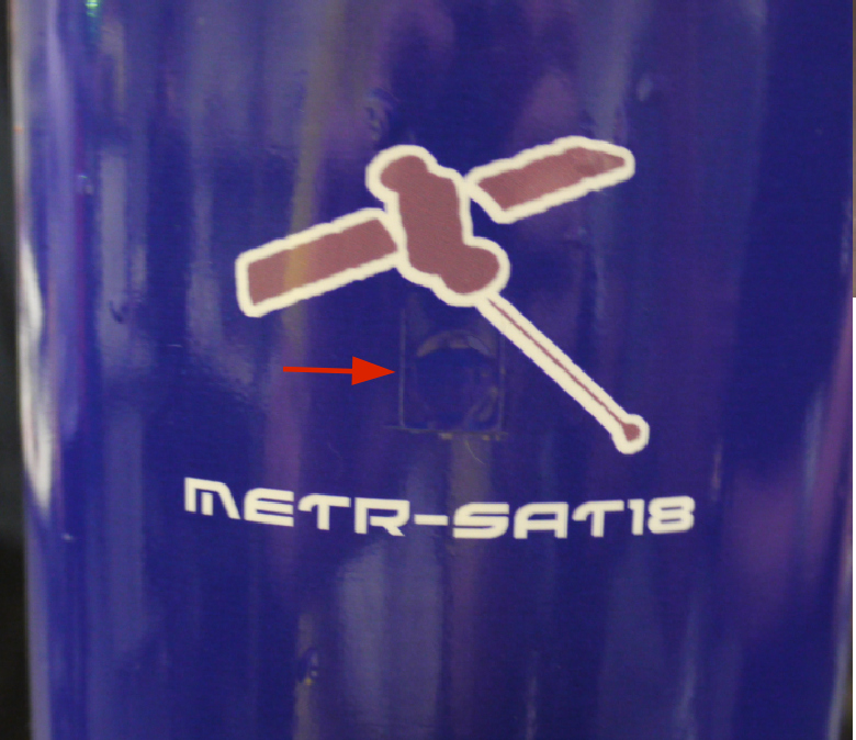
| To make the external appearance of the satellite more visibly appealing, a thin piece of adhesive vinyl was applied to the surface (Fig. 72). The vinyl sticker was digitally printed from 300dpi vector graphics artwork (Fig. 73) and laser cut to a size of 170 x 450 mm.
Why blue? The name “METR-SAT18” is short for “Mechatronics Satellite” and follows the naming convention of other satellites like InmarSat and CubeSat. |
 |
 |
|
 |
|
| The laser case and stalk were painted royal-blue to match the satellite body using common enamel spray paint. The nylon plastic material is quite porous but the paint covered reasonably well, even without a priming coat. The painted surface is still a bit rough (Fig. 77) and an extra prime-and-sand process would have improved the surface finish.
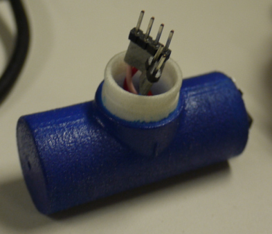
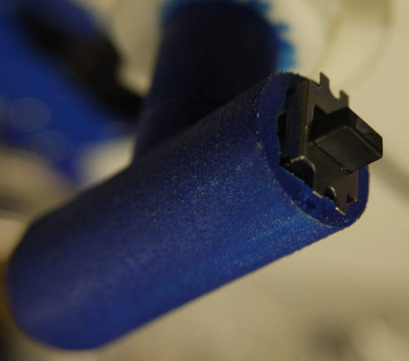
Wiring connectors were added so that the laser case can be disconnected from the stalk to allow installation of the battery module (Fig. 76). There’s a 2-pin connector for the laser and a 4-pin connector for the illuminated power switch. After applying the vinyl sticker to the body, the holes for the I.R. sensors (Fig. 79) were cut out using a knife. |
 |
 |
 |
 |
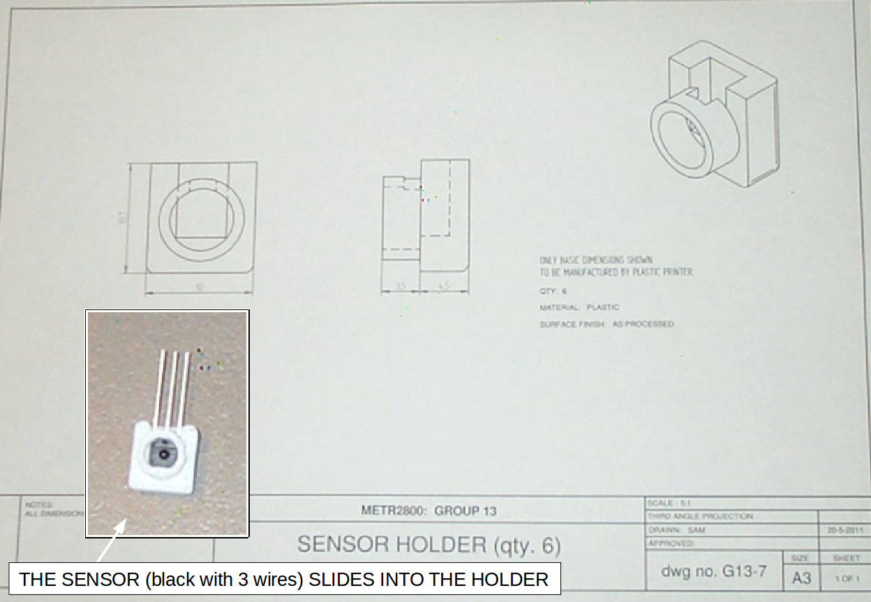
Each I.R. sensor is fitted into a holder made from nylon plastic (Fig. 80). The sensors are Osram SFH3160F 3-pin photo transistors with a maximum spectral response of 880nm. A photo-transistor induces a varying electrical voltage in response to light, and its sensitivity can be adjusted by using a variable resistor to set the current on the base pin.
The sensor holders fit into the satellite body with a “location” fit and are held in place with epoxy-based adhesive (Fig. 81). Because the white-colored plastic is slightly reflective, the sensor holders were painted with matt black enamel paint to prevent light bouncing around inside.
 |
 |
The power distribution and motor controller PCBs were installed on the underside of the motor support bracket using a single screw through each board (Fig. 82). The power distribution board (Fig. 83) has a filter and 5 volt regulator to supply “logic power” for the other circuit boards. The motor controller board (Fig. 84) has a 2 Amp H-Bridge driver for the motor and a transistor switch for the laser.
 |
 |
 |
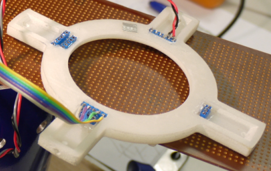
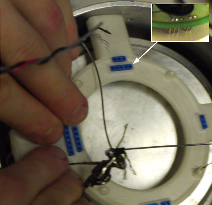
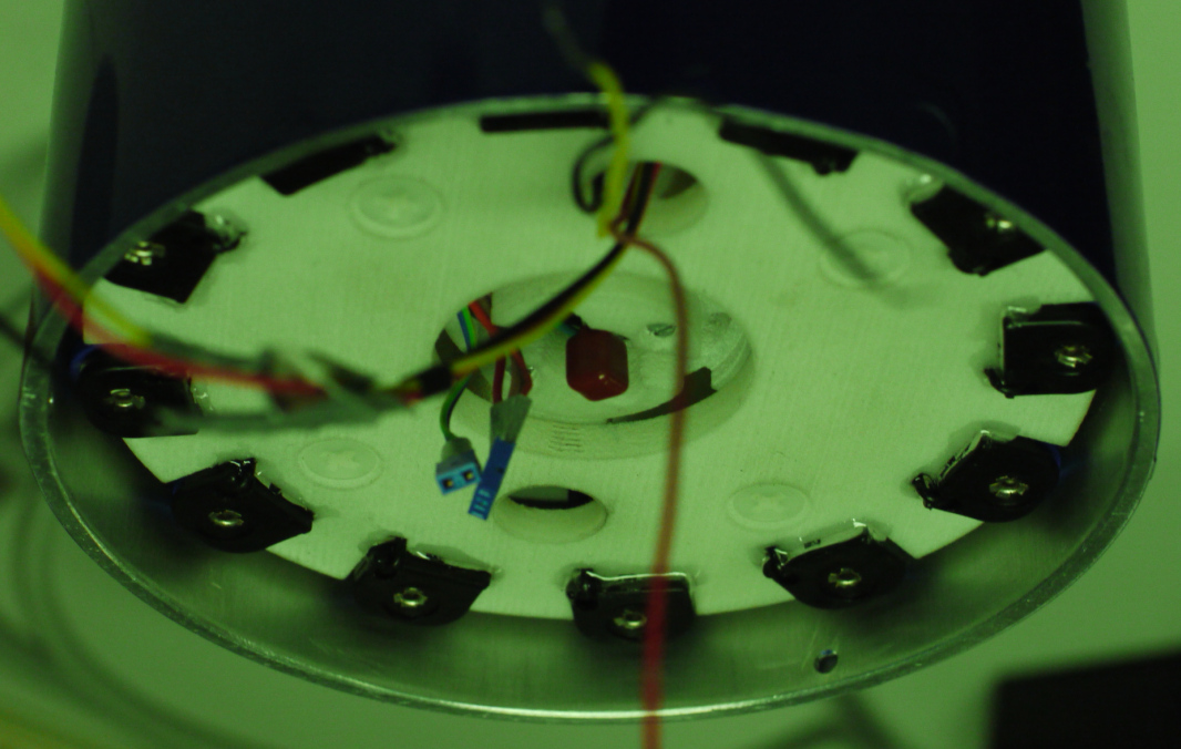
The main circuit board is located at the top of the satellite on a plastic support bracket and plugs into place using connector pins on the underside of the PCB. There are also 4 holes in the PCB for screws. The support bracket (Fig. 85) has 4 groups of female connectors (colored blue) that fit into cut-outs in the plastic. Each connector was soldered with wires that are routed to the I.R. sensors or to the other PCBs. The male PCB pins on the underside of the circuit board “mate” with the blue sockets in the support (Fig. 86). The support bracket is mounted to the satellite body using 4 x M3 countersunk screws.
 |
 |
 |
The electronic components on the mainboard were installed by hand soldering. SMT (surface mount) components were used to save space, with the passive components (resistors & capacitors) mounted on the underside of the PCB (Fig. 88) to give a more pleasing aesthetic appearance. The active components (microcontroller & LEDs) and electromechanical components (push button switches, potentiometers & piezo speaker) were all mounted to the top side of the PCB so they are easily accessible.
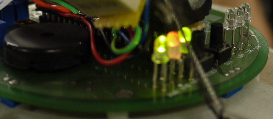
| The mainboard has 6 LED lights that indicate the status of the system: LED 1: 5 volt power available. LED 2: green = switched on, orange = ready to target. LED 3: flashing “heartbeat” at system clock frequency.
|
 |
 |
 |
 |
The battery module is installed by pushing it up into the bottom of the satellite (Fig. 93) and rotated clockwise to “twist-lock” securely in position.
 |
There is clearance between the underside of the battery module and the end of the satellite body, in order to fit the plastic end cap. |
 |
The last step of the assembly process is to install the laser stalk (Fig. 95). The laser stalk fits onto the end of the battery module bracket and held in place using epoxy adhesive. The laser case is attached using a grub screw and can easily be removed, in order to swap the battery module.
Testing the Satellite
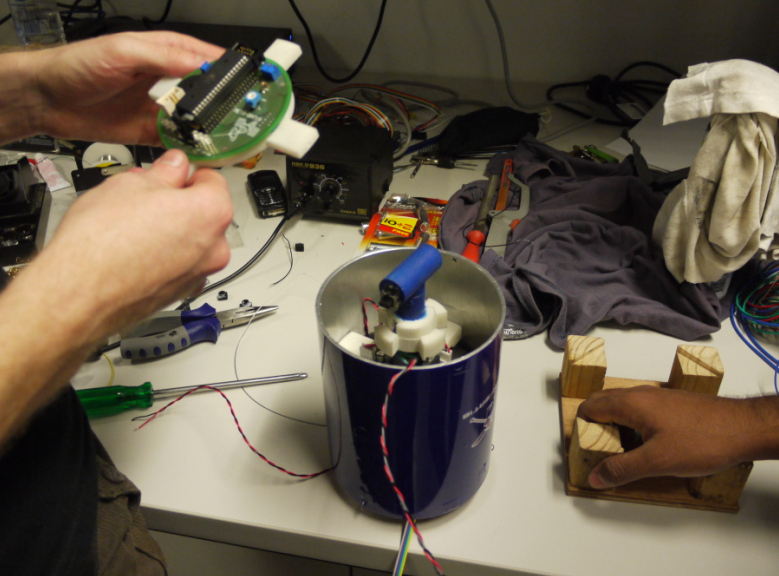
Once the satellite was assembled, lots of testing was conducted to tweak the software and fine-tune the targeting system. During testing the satellite was connected to a PC using ribbon cables (Fig. 96) so we could check the program status, change the code or issue commands via keyboard.
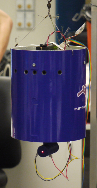
The satellite is suspended from a cable, which is high-strength “leader wire” from the fishing industry. Three wires were used to make a tripod-shape and secured at each end by creating a loop and crimping. The leader wire has multiple filaments with sharp ends (Fig. 96) and once testing was finished, the wire ends were trimmed and coated with epoxy (Fig. 106). A ball-bearing fishing swivel allows the satellite to spin without twisting the cable (Fig. 96).
 |
 |
Final demonstration
For the first demonstration, the satellite was hung from a cable and 4 targets positioned in a circle at varying distances.
| Each target consists of a paper bulls-eye stuck to a wooden backing plate. The actual target detected by the satellite is a cluster of 7 I.R. LEDs that fit into a hole through the wood at the top of the circle (Fig. 99). Because they emit infra-red light, the target LEDs are not visible to the human eye therefore a green LED indicates that the target is turned on. Note: Some of the photos below were taken using a camera that didn’t have an I.R. filter so the target LEDs are glowing red (Fig. 98). |
 |
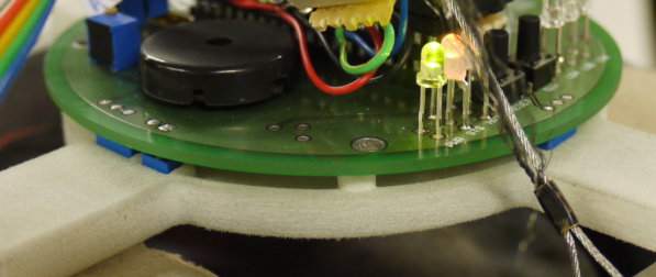
 The green LED indicates that the target is turned on and emitting I.R. light. |
 |
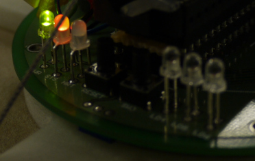
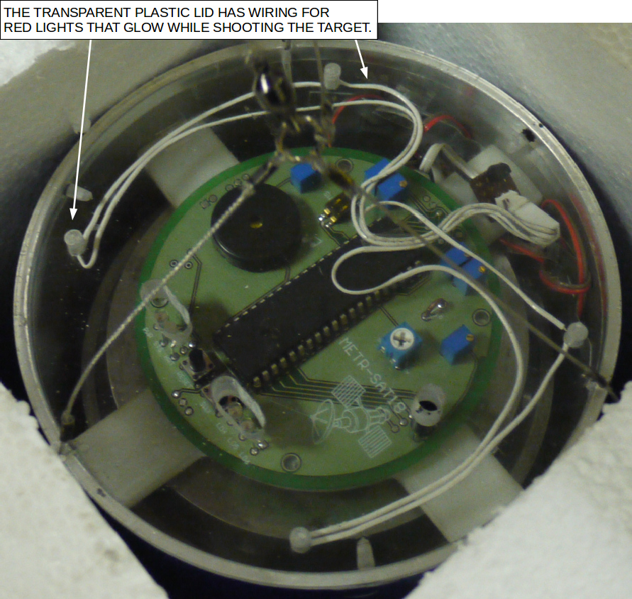
The targets were individually activated by a human operator and the satellite rotates slowly until it detects the infra-red light from the target using its primary I.R. sensor. When a target is detected, the satellite locks onto the target direction using an array of 5 I.R. sensors. The top cap of the satellite has 4 red-colored LEDs that glow red at the same time as it activates the laser (Fig. 100 – 101).
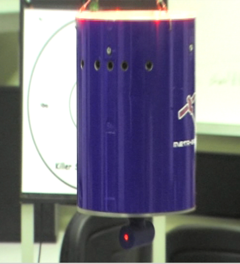 |
 The PCB has 7 x I.R. LEDs and one green LED. |
 the bull-eye. |
Packaging the Satellite in a Box
For transportation, and as an exercise in product presentation, the satellite was packaged in a custom-made box. The satellite sits on its wooden base, to protect the laser stalk that hangs from the bottom. Scrap pieces of polystyrene foam were cut to pad the empty space in the box.
 |
 |
 |
 |
Experiments with high-power laser
For the second demonstration, the low-power 1mW laser was replaced by a high-power 445nm U.V. (Ultra Violet) laser. The paper targets were replaced by balloons and the goal of the demonstration was for the satellite to “pop” all the balloons.
Warning: Don’t try this at home, lasers are not toys. This experiment was performed in a controlled environment whilst wearing appropriate PPE (Personal Protective Equipment).

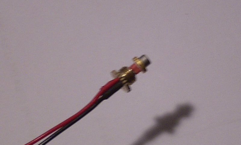
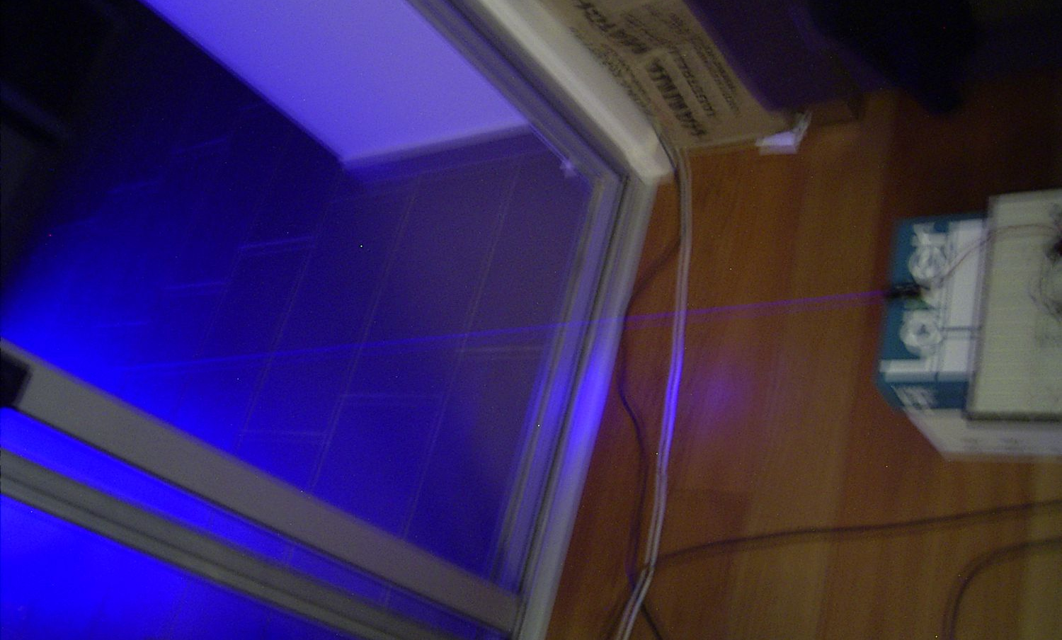
The laser driver pulls more than 1 Amp of current and is powered by an external power supply (the gray wire in Fig. 109). The satellite’s onboard batteries can’t supply sufficient current, whilst also powering the motor, without causing a current “dip” that causes the microcontroller to reset. For testing, both the lasers were mounted together on the satellite; the 1mW laser was used to conduct a “dry run” of target practice, then the high-power laser was activated for the final test.
Each target consists of an I.R. transmitter (the same used in the first demonstration) with a red balloon hanging below it. To burst a balloon the laser beam must be concentrated on the balloon’s surface for approximately 2 seconds, due to the reflectivity of the red-colored balloons.
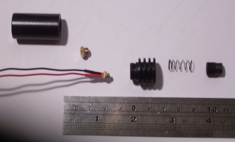
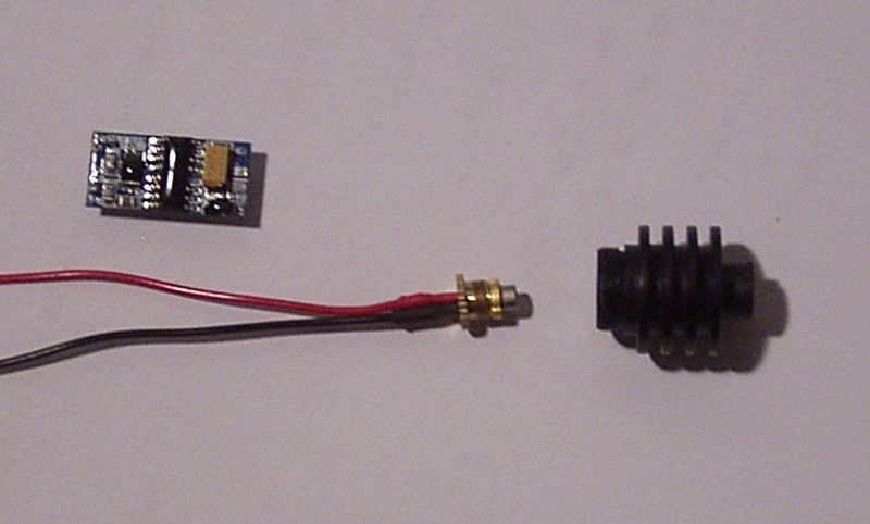
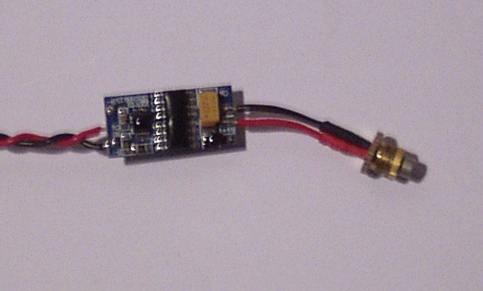
The 445nm UV laser diode was salvaged from a DVD burner. A suitable driver board was sourced and the laser diode is driven with sufficient current to provide about 1W of output power. The diode and driver were assembled in an aluminum case that acts as a heatsink.
 |
 |
 |
 |
 |
 |
To watch this demonstration, see Video 1 at the top of this page. Some screenshots are shown below (Fig. 116 – 117).
 |
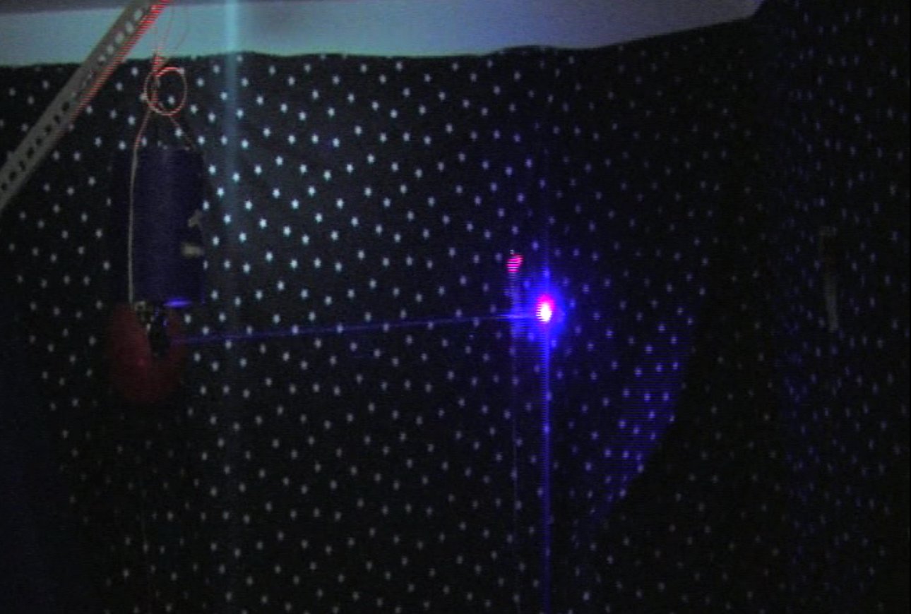 The video camera is missing an I.R. filter so you can see the red-colored light from the I.R. target, and the UV laser appears to be purple. |
This project was undertaken at the University of Queensland in 2011 with S. Hinton, J. Jangam and K. Lawson.
Design report:

D. Butterworth, S. Hinton, J. Jangam and K. Lawson, “Satellite Defence System Prototype – Design Report”, un-published, 2011.
PDF