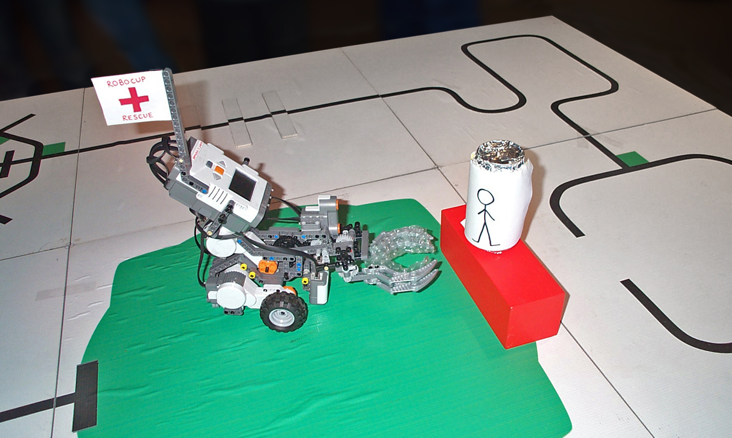
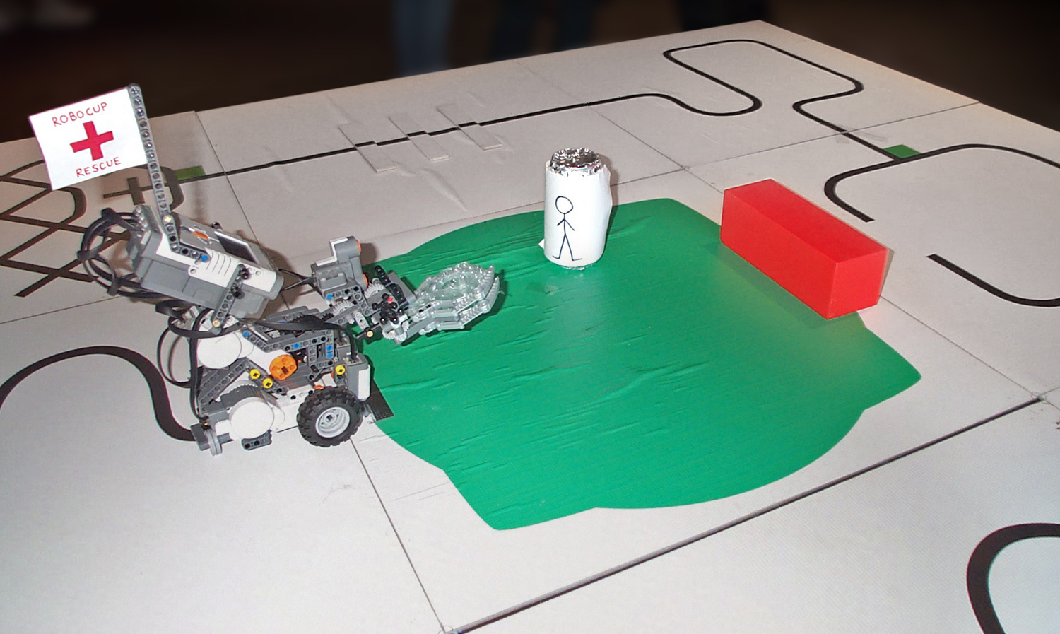
RoboCub is an annual robotics competition with multiple domains including Soccer and Rescue. This mobile manipulator robot (Fig. 1) was developed as a demonstration for the “Premier Rescue” competition in the RoboCup Junior division. The goal of the competition is for the robot to autonomously navigate to a chemical spill, find a person and carry them to safety.
.
Note: the competition has since expanded and the rules changed from what is described here.
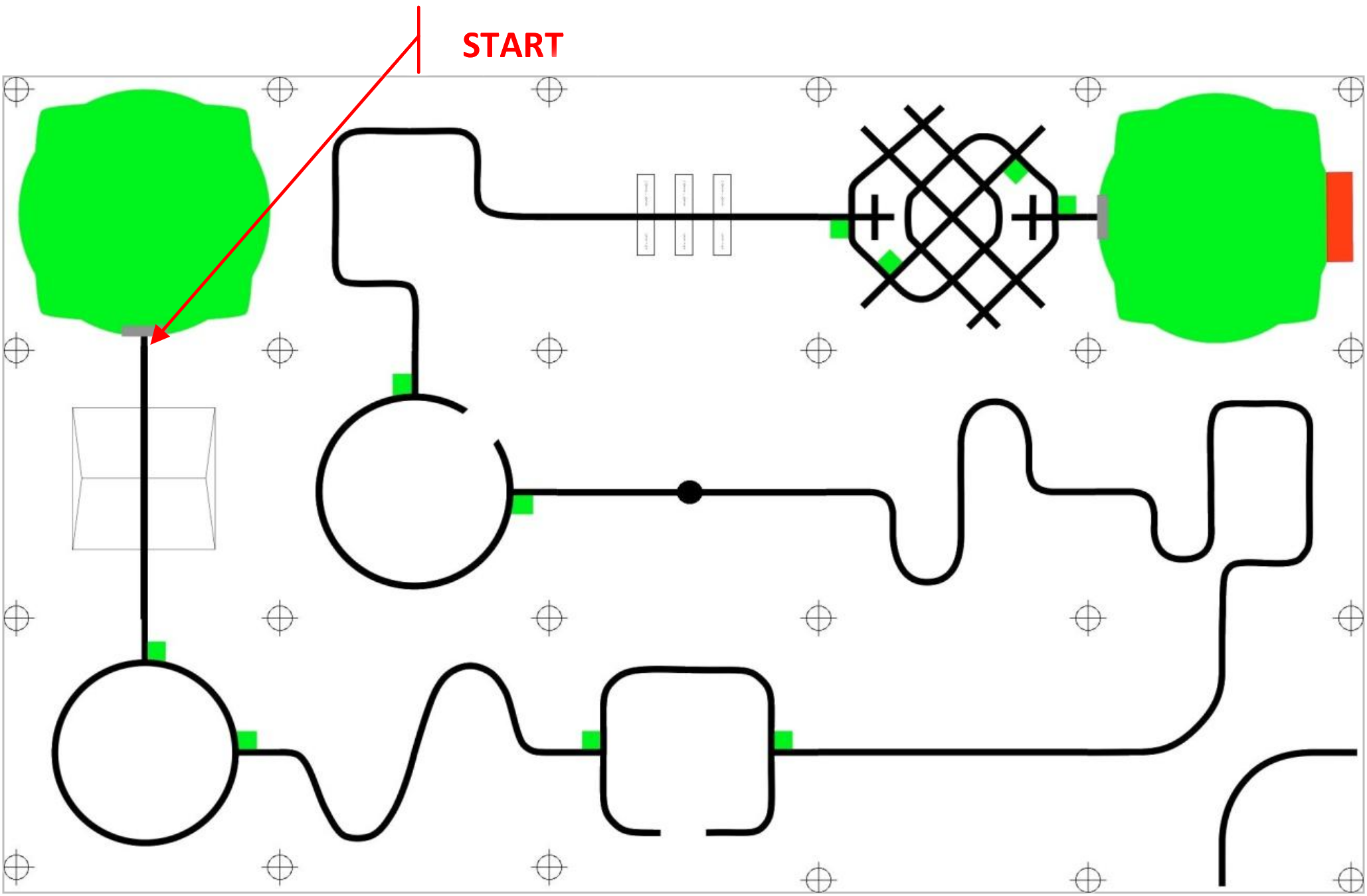
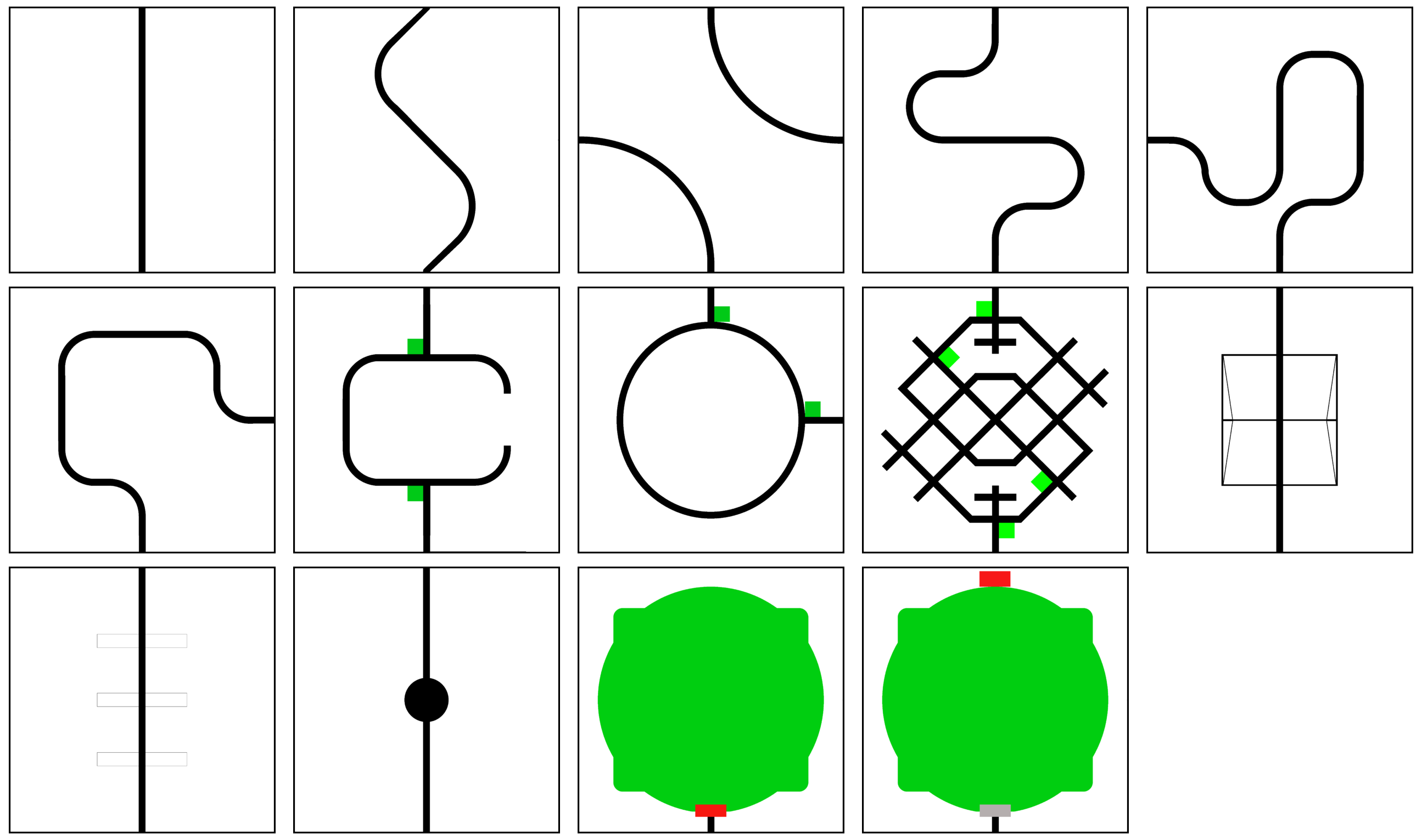
The competition arena consists of a path constructed from tiles (Fig. 2).
You can view the tile graphics here or download all information in a ZIP file.
You can view the tile graphics here or download all information in a ZIP file.
.
The robot must follow a line and obey coloured markings on the ground. It must also navigate past obstacles including bumps, a hill and a semi-transparent bottle of water. At the end of the course the robot must “rescue the victim”, which involves finding an aluminium drink can, grasping it and placing it on top of a platform.
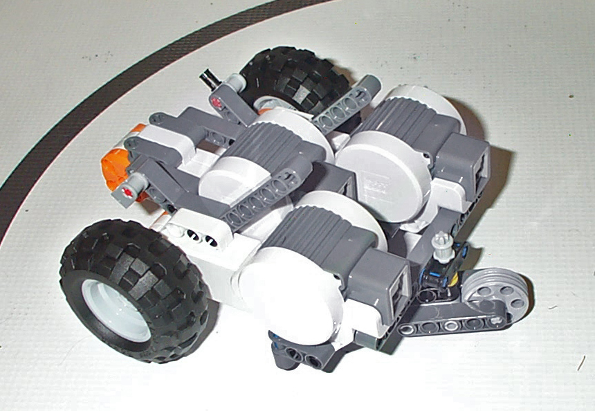
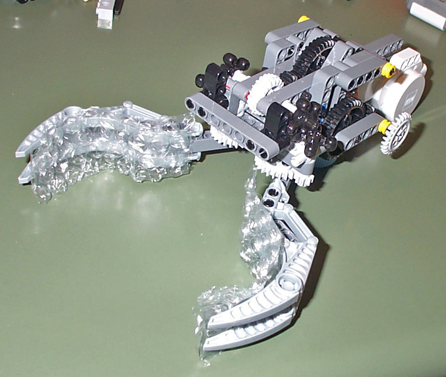
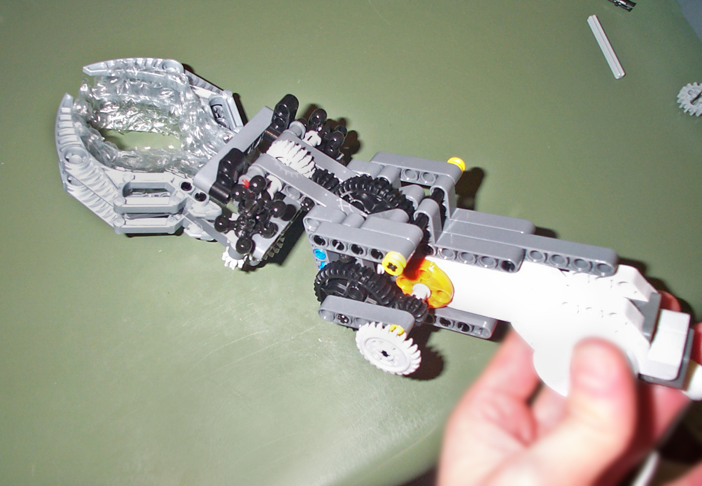
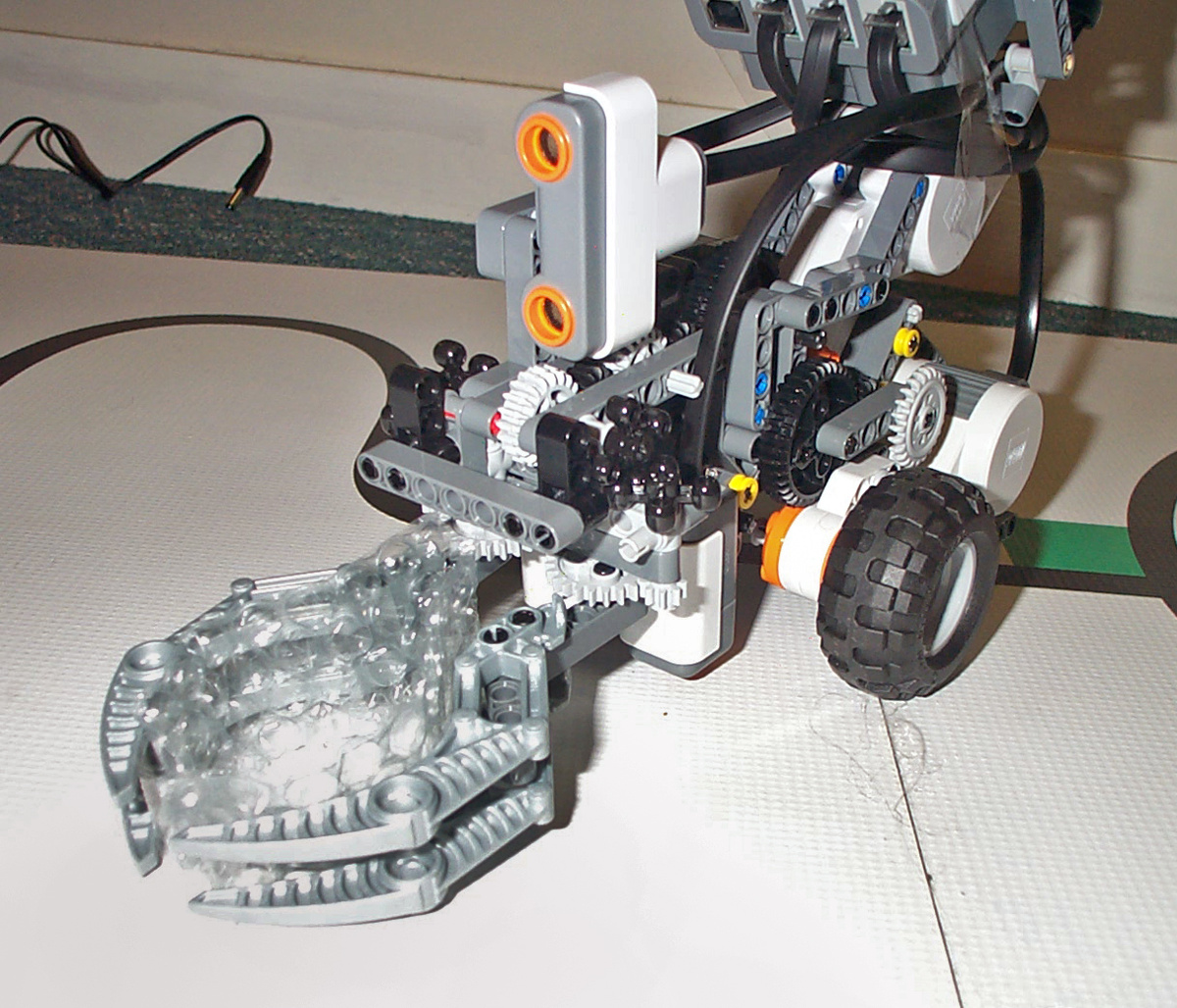
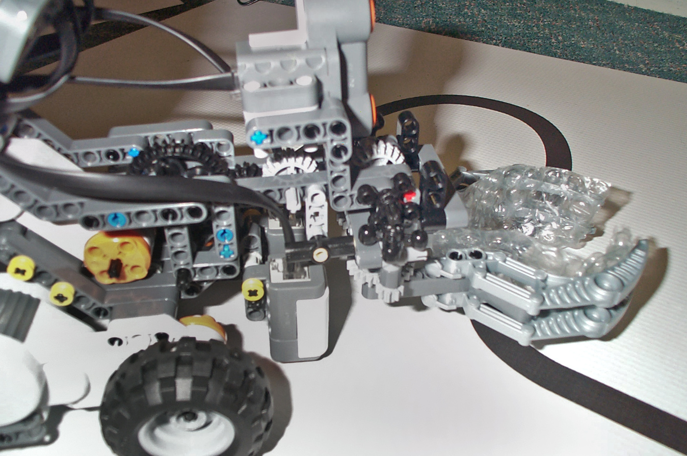
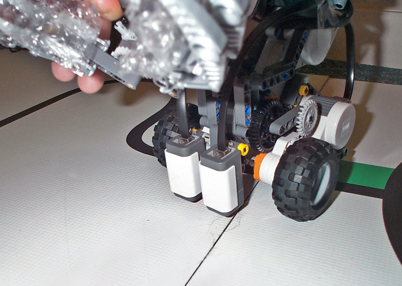
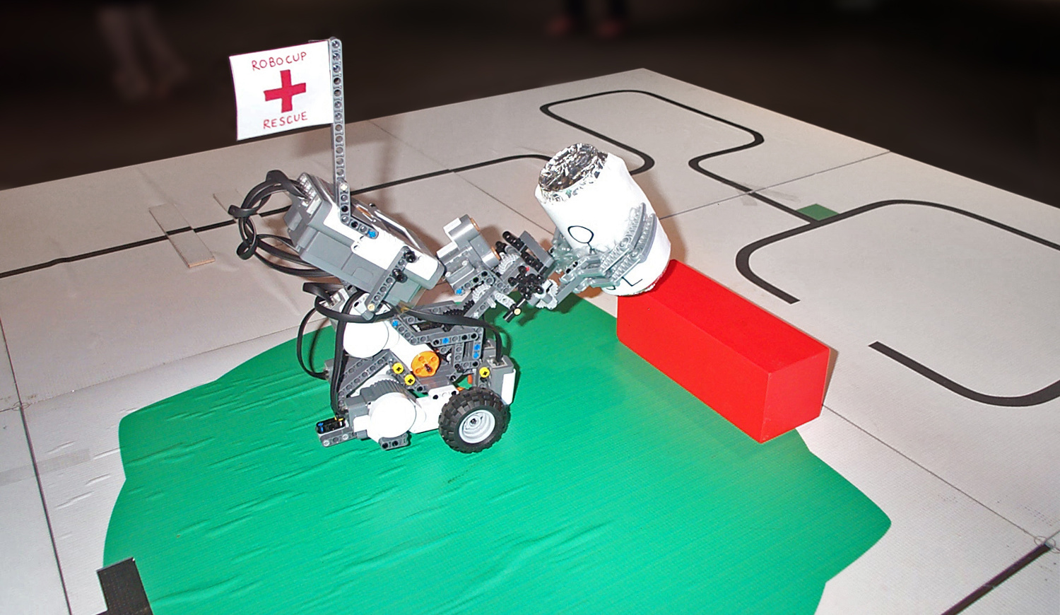
The demonstration robot (Fig. 1) was programmed in RobotC language, running on custom firmware installed on the Mindstorms NXT Brick. The robot’s base utilizes two drive motors (differential drive) with a caster wheel on the back (Fig. 3). The gripper (Fig. 4) is designed to pick-up cylindrical objects and is made using a set of Claws lined with Bubble Wrap. The gripper and lifting mechanism are actuated using a third motor. When the motor rotates, the jaws close around the object. If the jaws can’t close any further, a small bevel gear is free to climb over a larger gear and the lifting arm tilts upward (Fig. 5).
 |
 |
 |
An ultrasonic distance sensor (Fig. 6), also called a range finder, is used to detect objects in front of the robot. A pair of I.R. (Infra-Red) light sensors on the front of the robot (Fig. 8) are used for line-following and to detect colored patches.
 |
 |
 |
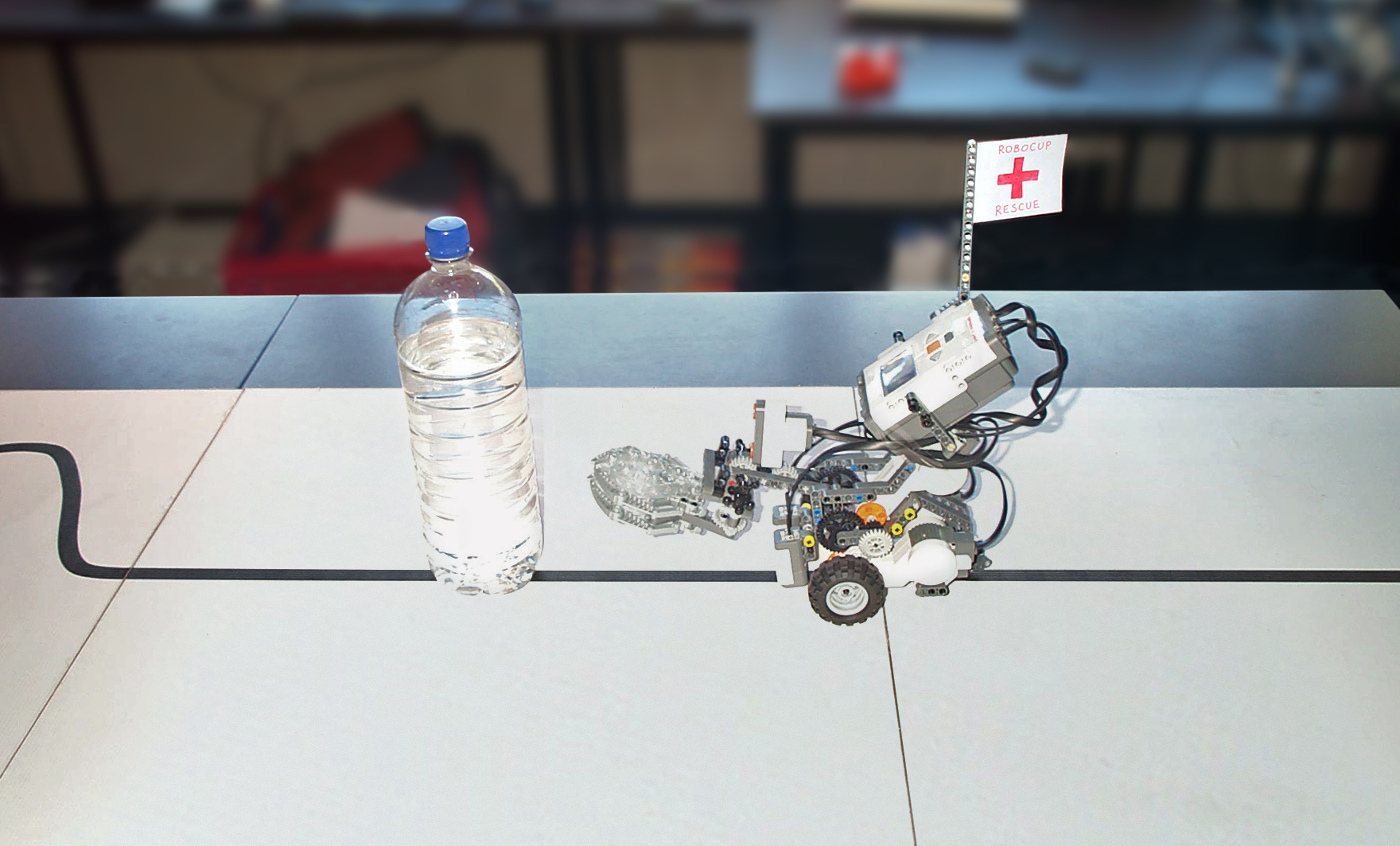
The robot follows the black-coloured line whilst driving forward as fast as possible. It continuously checks for obstacles using the ultrasonic sensor. When the robot finds the water bottle blocking the path (Fig. 9), a sub-routine controls the robot to drive in an arc shape around the obstacle using dead-reckoning.
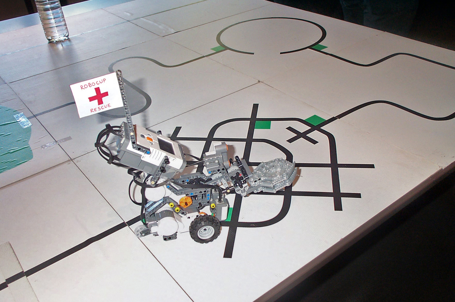
The system also checks for perpendicular lines across the path which indicates the robot is on a special tile, such as the “Dead End”, “Roundabout”, “Gridlock” or the “End” tile (chemical spill). A sub-routine checks the pattern of colors to confirm where the robot is and then a task-specific function is executed. For example, to negotiate the gridlock pattern (Fig. 11) the robot must detect multiple green-coloured patches and turn right/left/right/left. The standard light sensor actually works better than the RGB sensor for detecting colors because it provides one value for the incident light reading.
 |
 |
 |
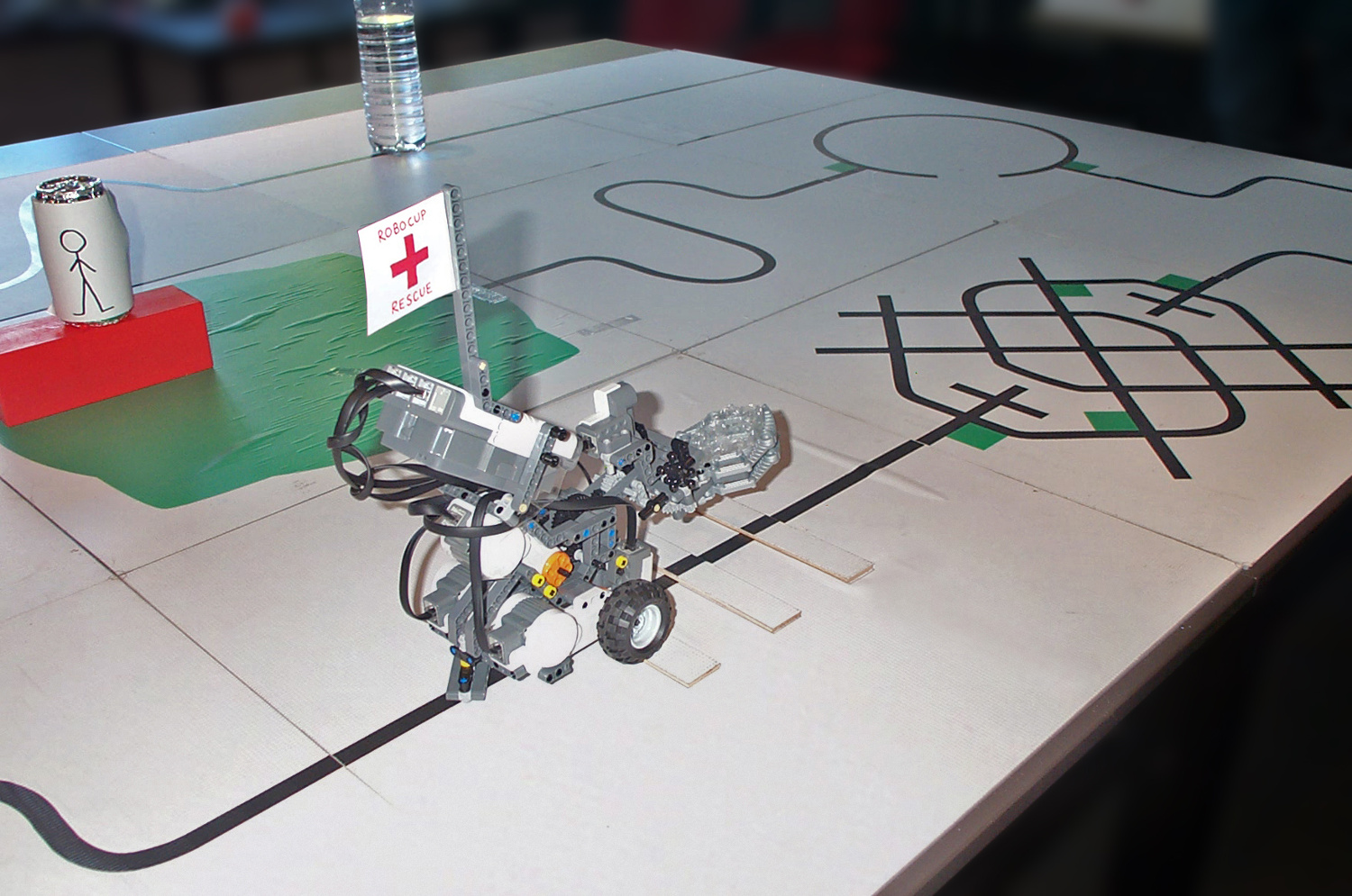
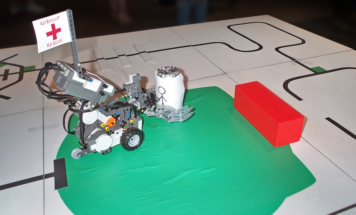
When the robot reaches the chemical spill (Fig. 12) it finds the “victim” (drink can) using the ultrasonic sensor. It rotates in a 180 degree arc and takes multiple distance measurements in order to build a 2D map of the area. The robot drives towards the can (Fig. 13) and picks it up (Fig. 14). Then it drives towards the platform, using dead-reckoning and trigonometry to calculate the required angle and distance to move. Lastly, the can is released onto the platform.
 |
 |
 |