This page summarizes some of my prior R&D work and academic research in robotics:
Grasping & Manipulation
CNC Machine Tending using Mobile Robot
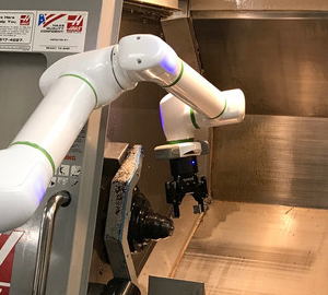
Fig. 1: Robot using 3D vision for parts loading.
Existing systems for automatic loading and unloading of a CNC machine use customized part feeders and stiff industrial robots. In contrast, this work looked at developing a generalized system for mobile pick-and-place, enable autonomous low-volume manufacturing.
The robot comprises of a 6-DOF “collaborative” arm and a differential-drive mobile base. A 2D LiDAR sensor is used for localization to a known map of the work area. A structured-light sensor mounted above the arm allows the robot to recognize and detect the pose of known objects. Additional sensors on the robot’s wrist allow it to more accurately recognize and position objects in the CNC Power Chuck. The robot successfully demonstrated autonomous navigation between work stations, grasping parts from a container, stowing items on the mobile base and loading blanks into the CNC Lathe.
Mixed Bin Picking of Metal Parts
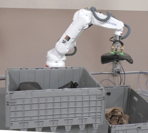
Fig. 2: Robot system sorting metal parts.
In factories and warehouses, a lot of time is spent moving objects around. This includes unpacking objects from pallets and skids, picking objects from inside bins and totes, and placing or stacking objects into containers. In this work we investigated using a robot to automatically stack and unstack metal parts, which can be challenging because they have a plain, reflective surface that is difficult to “see” using some types of vision sensors.
A 6-DOF industrial robot was used for the demonstration, with a structured-light 3D sensor mounted overhead. The gripper consists of 3 compliant suction cups and a vacuum pump. A custom motion planner was developed that leverages the manipulator’s closed-form kinematics. The system demonstrated the ability to automatically detect the pose of metal objects, pick or place them inside a plastic container, and align parts on a hook.
DARPA Robotics Challenge
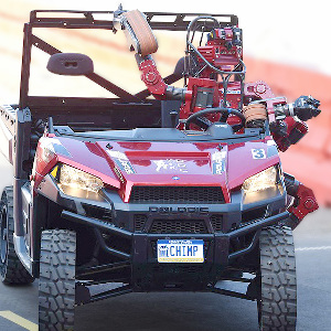
Fig. 3: Robot arrives on-site using an ATV.
A program funded by the Defense Advanced Research Projects Agency to develop a robot capable of performing repair tasks in industrial environments that are too dangerous for humans. I was a member of the Carnegie Mellon Tartan Rescue team and we developed a mobile manipulator robot called CHIMP (CMU Highly Intelligent Mobile Platform).
The robot is ambidextrous and can use a tool with either arm to cut through a wall.
CHIMP was also the only robot capable of falling over and standing back up again.
We scored 3rd place in the finals and won a $0.5 million prize.
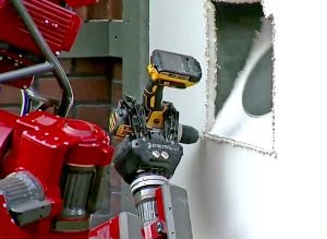
Fig. 4: Robot using cordless drill with cutting bit.
For a robot to operate in the real world among humans, it would be useful if the robot could use existing tools and equipment designed for humans. This would allow human-robot collaborative workers to share the same tools. Or in an emergency scenario, a robot could ideally make use of whatever tools and equipment are found laying nearby.
In this work we develop a system for an autonomous robot to grasp, manipulate and operate a power drill. The robot successfully picked-up the tool, squeeze the trigger, drilled and cut a squared-shaped hole in a panel of drywall (plasterboard).
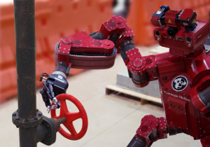
Fig. 5: Robot turning a wheel handle to open a gate valve.
A useful capability for an inspection or service robot is to open or close valves of the type found on steam or hydraulic pipes in an industrial environment.
This work describes a system for an autonomous robot to detect valves and turn them using a 7-DOF manipulator. Various perception algorithms were tested using camera and/or LiDAR sensor. The robot was successfully able to turn various types of valves, including lever handles, and small, medium or large wheel handles.
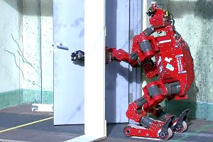
A robot that can open doors would be useful for applications in search and rescue, building maintenance and personal assistance. The most difficult door for a robot to “see” is one where the door surface is flush (co-planar) with the surrounding wall. And heavy, spring-loaded doors are the most challenging for a robot to physically open.
In this work we develop a door detector using camera-based vision and laser sensing, and discuss our work on motion planning to enable the robot to automatically pull open a door.
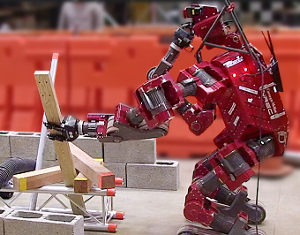
Fig. 7: Robot extracting a piece of lumber from a pile by pulling it in a specific direction.
A mobile robot might encounter some object or debris blocking its path. This work focuses on the situation where the robot can individually manipulate the objects to clear a through-path. This manipulation problem is similar to pick-and-place of unknown objects, however the objects must be selected in a particular order, then lifted and extracted in a certain manner. This makes solving the overall problem time-consuming to solve with existing algorithms.
In this work we leverage the strengths of both the robot and the human operator. The operator’s intelligence is used for overall task planning and a guided-autonomy system was developed for mobile pick-and-place of unknown or unmodelled objects.
To accomplish tasks like assembling a piece of furniture or clearing a table requires successfully performing a set of sub-tasks in a particular order. For example, it’s not a good idea to remove the table cloth before the wine glasses.
For a robot to perform a multi-step task like this also requires planning each sub-task in detail. For example, if the robot is not close enough to manipulate one particular object, it could fail to achieve the overall task.
This work presents a system for task planning and error recovery, demonstrated using a dual-arm mobile manipulator designed for personal service applications. The robot was successfully able to clear a table by moving some dinnerware onto a tray, then lifting the tray using both grippers.
This was a team project at the CMU Personal Robotics Lab.
Constrained Task-Space Planning using IK Search
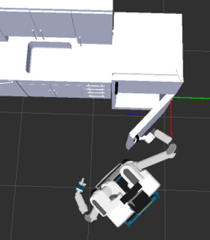
Fig. 9: Opening a fridge door, which requires a multi-step sequence where the robot’s gripper moves along a straight path, then a curved path.
Typical methods for motion planning with high-DOF robot manipulators use a random-sampling approach. This results in long planning times and unpredictable results. For planning motions where the manipulator is constrained in task-space, the planning time is even longer.
In this work we consider 5/6/7-DOF manipulator designs where there is a closed-form inverse-kinematic (IK) solution. The planner samples from IK solutions that satisfy the task-space constraint, then interpolates in joint-space.
The planner was demonstrated on a 7-DOF manipulator, which has redundancy in the joint-space. Successful motion plans were generated for a set of common object
manipulation tasks: lifting, pushing, pulling, sliding, poking, turning a lever, and opening
a fridge door by pulling the handle.
Note: A similar IK-based planner was subsequently incorporated in the Robot Operating System (ROS).
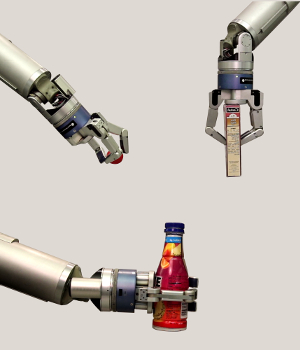
Learning a Grasping Policy using Geometric Features
Fig. 10: Examples of 2 grasp types: a 3-finger “precision” grasp, and a “cylindrical-power” grasp with a horizontal or vertical approach.
A robot gripper is only capable of performing a small number of grasps, compared to the human hand. Using a specific gripper, an object can be picked-up using only a sub-set of those grasp types. For example, a dexterous multi-finger hand can securely hold a mug via the handle, whereas a 2-finger gripper should pinch the rim. Some objects can not be grasped at all, if they are too large or too heavy.
In this work we train a robot how to grasp some common household objects. The goal is to learn the mapping between grasp primitives and the semantic properties of an object. The robot has a Barrett Hand, which has 3-fingers and 4-DOF. The hand can perform 7 grasp types, each defined by a “preshape” configuration of the fingers. Using experimental trials the robot discovers which objects it can pick-up. We also trained a classifier to learn a grasping policy for unknown objects, using the object’s geometric properties as features.
This work was undertaken at Carnegie Mellon University.
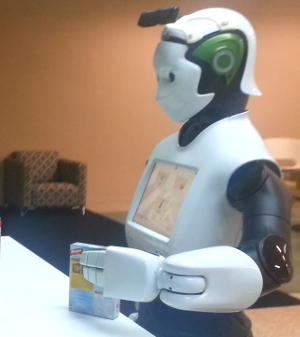
Grasp Planning using Minimum Bounding Box
Fig. 11: Robot about to pickup a box of food.
Many robot hands and grippers have a simple parallel mechanism or underactuated fingers. This means the gripper can be either “open” or “closed”, and is only capable of performing simple “power” grasps.
We developed a simple online grasp planner that finds the thinnest part of an object and checks if there is a collision-free pose for the open gripper. The scene is scanned using a 3D depth sensor and segmented to get separate point clouds of unknown objects. The planner searches to find the 2 parallel faces with the minimum width, similar to the “rotating caliper” algorithm.
The method was tested using the REEM-H robot, which was successfully able to grasp various unknown objects. The hand has 2 underactuated fingers and a fixed thumb. A velocity-based grasp controller was developed which closes the fingers until movement stops.
This work was undertaken at PAL Robotics.
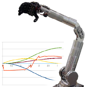
Trajectory Planning for 6-DOF Manipulator
Fig. 12: Manipulator arm, with 5-finger hand. (inset) Plot showing joint angles Vs. time.
The light-weight 6-DOF manipulator called HUBO-ARM was developed for service robotics applications. This work describes the implementation of task-space motion planning and joint-space trajectory generation for this robotic arm. The robot and the surrounding environment are modelled using 3D geometric primitives. Collision-free motion plans are generated using RRT or SBL, and the resulting joint trajectories are smoothed using cubic splines. The system was able to plan and execute successful motion plans, both in simulation and on the real robot.
This work was undertaken at the Humanoid Robot Research Center at KAIST.
Computer Vision
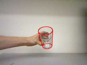
Detecting transparent or textureless objects
Fig. 13: The detected pose rendered in 2D.
Computer vision algorithms have traditionally focused on detecting objects that have some surface texture. However there are many objects in the home that are transparent or textureless, such as a glass cup or plain coffee mug. Or in industrial environments, objects such as fasteners and sheet metal parts. Futher complications are that objects made of glass or metal can “trick” the sensor, due to specularities or reflectivity.
In this work we utilise a prototype structured-light 3D sensor that uses a novel single-line imaging array that rejects light from non-direct reflections. A glass cup is modelled using a triangle mesh for a simple cone shape. Model-based tracking is performed using the depth image and the performance compared to an off-the-shelf 3D camera.
Detecting Holes in Objects using Graph Theory
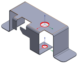
Fig. 14: Two holes are recognised in this object.
For object manipulation it is useful to know if an object has any holes in it, such as the handles and opening of a cup, or for performing a peg-in-hole task. The object is modelled in 3D using a triangle mesh, comprising of vertices and edges. The model is generated from CAD or a 3D scanner. The goal is to automatically recognise any holes in the geometry of the object, as opposed to manually annotating them in the model.
Our proposed method is to find the boundary edges in the mesh, build an an undirected graph, find the cycles (loops) using Tiernan’s algorithm, then perform some simple filtering to get the 3D pose of each unique hole. The method was successfully used to recognise holes in complex mesh models of objects with numerous round and oval-shaped holes.
Robust Color-based Object Detection
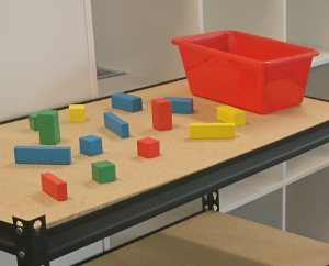
Fig. 15: Colored blocks on a table.
Detecting objects based on their color might seem like a simple problem, however what a camera detects as “color” is dependent on light, shadow and the object’s surface properties. An ideal color detector would be robust to these factors, without controlling the lighting in the local environment or using online color calibration.
In this work we compare 3 approaches: classification using color histograms, LAB-space classification using a Gaussian Mixture Model (GMM), and a novel method using a parts-based model based on image segmentation by color quantisation.
Analysis of Fundus Images using Deep Learning
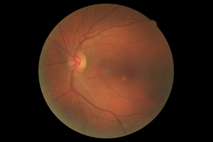
Fig. 16: Image of the inside-back surface of an eye.
Diabetic retinopathy is damage to the blood vessels in the rear area of the eye, caused by diabetes. This condition can be diagnosed by examining specialized photographs of the inside of the eye called fundus images. In this work we investigate using deep learning to automatically classify a dataset of fundus images. The images were pre-processed using traditional computer vision techniques, and a CNN (Convolutional Neural Network) was developed based on the ResNet architecture.
This was a team project with S. Mukherjee and M. Sharma.
Improved PnP Algorithm for AprilTag
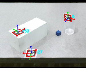
Fig. 17: AprilTags detected from camera image.
Fiducial marker systems, such as ARTag and AprilTag, can be used for numerous robot perception applications including map localisation, visual servoing control and object detection. The Perspective-n-Point (PnP) method is used to find the 3D pose for the tag, based on detecting some coplanar points of the tag in a 2D camera image.
However, for a camera-only vision system doing “one shot” detection of individual markers, there are multiple failure modes where the PnP algorithm can fail in-practice.
In this work we compared various PnP algorithms from the literature and developed an improved system for detecting AprilTag markers.
Benchmarking of 3D Depth Sensors
Fig. 18: Testing a Primesense Carmine sensor.
Traditionally a robot uses a laser-based LiDAR sensor for perception, such as those made by Sick, Hokuyo or Velodyne. More recently an increasing number of 3D sensors are available, such as industrial-grade time-of flight (TOF) and consumer product 3D depth sensors.
Typically each sensor is supplied with narrow performance characteristics, so we need to develop new methods for benchmarking their relative performance at detecting multiple types of objects at varying distances.
As part of multiple projects, I have analysed numerous sensors, including: Hokuyo UTM-30LX LiDAR, 3D camera pairs, IFM O3D TOF, MESA Imaging TOF, Microsoft Kinect, Kinect v2, Asus Xtion, Orbec Astra, and Structure IO.
Path Planning & Navigation
Global Pose Initialization in LiDAR Map
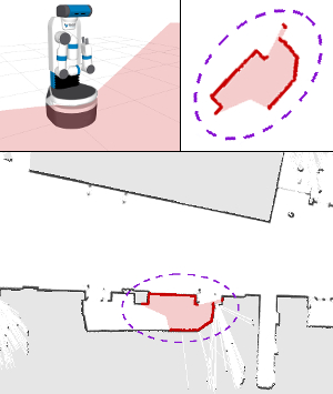
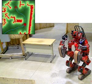
Fig. 19: Finding the robot’s initial pose in a map.
The laser scan (top) is compared to the static
grid map to find the best match (bottom).
When a mobile robot is powered-up it needs to determine its location within a map of the environment. Ideally the robot would automatically recognize known features in the nearby area, rather than initializing the pose using a GPS or human input. This is called global localization or the “wake-up robot” problem.
This work focuses on robots that navigate using a 2D LiDAR sensor. The known environment is represented by a grid map that was captured using a laser-based SLAM system. Various algorithms for global feature matching were compared, including template matching and the FLIRT descriptor. The first scan from the 2D laser sensor is compared with the static map to find the pose with the highest correlation. If there is more than one candidate, the MCL (Monte Carlo Localization) system is initialized with multiple hypotheses. The algorithms were evaluated using data from the Freiburg 2D Laser Dataset and experiments were conducted using a Fetch mobile manipulator.
Generating Graphs from a Voronoi Diagram
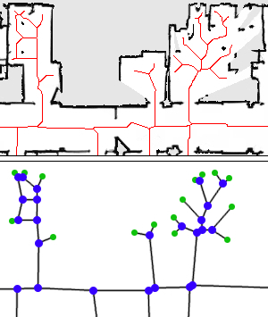
Fig. 20: Converting a voronoi diagram to a graph. (top) Discrete voronoi diagram of a 2D LiDAR map. (bottom) The resulting voronoi graph.
A topological map is a graph of locations (places) and the connectivity between them. This enables a robot to solve global motion planning problems such as how to move from “Room A” to “Room B”. In this work we develop a method for automatically generating a Voronoi Graph from the robot’s 2D static map. The map is a 2D raster image produced by localization methods such as LiDAR-based MCL or SLAM.
The method works on a 2D image. A discrete Voronoi Diagram is generated, also known as the image skeleton or medial axis. Various algorithms were compared, including the Zhang-Suen and Guo-Hall thinning algorithms, Beeson’s EVG-Thin and Lau’s Dynamic Voronoi. The intersections and branch end-points are detected using template matching. This is more robust than simply counting pixel connectivity and works with skeletons having 4- or 8-connectivity. The final graph is constructed by labelling the pixels using Connected Component Analysis.
Path-following Control using NMPC
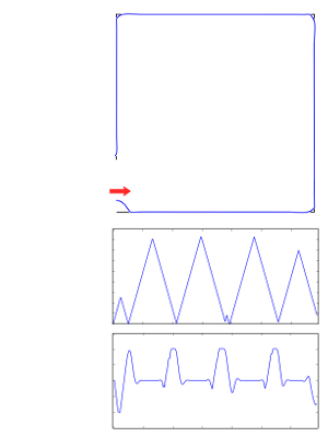
Fig. 21: The robot follows a square path, including sharp corners that require turning in-place. (top) Actual path (blue) over desired path (black). (bottom) Robot’s forward and angular velocity.
Typical methods for path tracking include pure pursuit control and trajectory roll-outs (motion primitives), however the robot does not follow the path precisely. In this work we investigate path-following control, where the objective is to simultaneously minimize the path deviation (offset distance) and maximize the forward velocity (progress) along the path.
A path-following controller was implemented using Non-linear MPC (Model Predictive Control) and the robot was successfully able to follow a square-shaped path. The controller was tested both in simulation, using ROS Gazebo, and on a real robot. If the robot starts away from the path (see red arrow) it will first drive onto the path. To move around sharp corners, the robot’s forward velocity goes to zero whilst a high angular velocity makes it rotate.
The robot is based on a modified wheelchair. A unicycle motion model is used to represent the differential drive. A pair of Roboteq brushed DC motor controllers are connected to a laptop computer via RS-232 serial. The MPC algorithm was implemented using the ACADO Toolkit and runs in real-time on Xenomai Linux. A LiDAR sensor is mounted high on the robot, providing accurate localization within a static map.
Autonomous Navigation for Mobile Robot
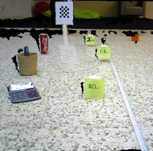
Fig. 22: Robot navigating around obstacles. (inset) The output from the path planner.
A mobile robot must be capable of driving autonomously between two locations without hitting any obstacles. In this work the robot uses its LiDAR sensors to generate a 3D model of the world. The operator specifies “go to this location” and the robot automatically plans a path along the shortest route and safely navigates to the destination.
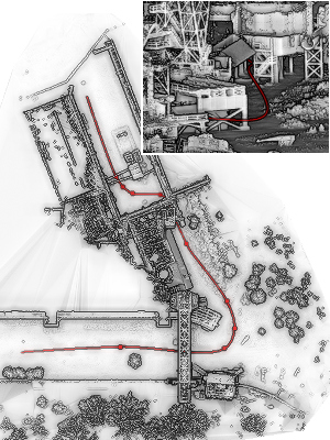
Fig. 23: A path (red) generated by the planner, enabling a drone to fly through an industrial plant. (inset) Close-up of the LiDAR model and the path going underneath an overhanging structure.
A LiDAR scanner can be used to generate detailed models of very large environments, such as a city or urban area, a factory, industrial plant, or agricultural farmland. A robot can use this high-resolution LiDAR map to determine its current location and relative motion, using SLAM (Simultaneous Localization and Mapping).
In this work we develop a mission planning system for finding a path through these large point clouds, enabling a robot to navigate between two locations. The planner uses a combination of random-sampling, rejection-sampling and optimization. The final path must satisfy user-specified constraints, such as curvature, altitude, total distance and GIS overlays with semantic information.
Experiments were conducted using a light-industrial UAV (Unmanned Aerial Vehicle) from DJI, whereby the drone was able to safely fly in-between obstacles like trees and buildings, and under overhanging structures like bridges, powerlines and doorways. Potential applications include inspecting infrastructure, monitoring crops, self-driving cars and delivery robots.
This work was undertaken in the Field Robotics Center at Carnegie Mellon University.
Obstacle Avoidance using Pre-computed Alternative Paths
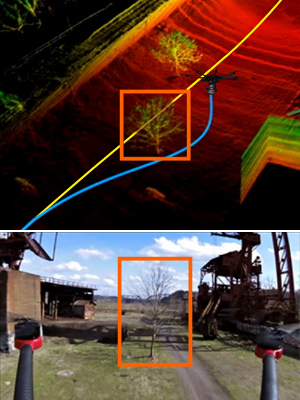
Fig. 24: Autonomous UAV flying around obstacle. (top) LiDAR map of environment. The drone is following the main path (yellow) then switches to an alternative path (blue) to avoid hitting the tree. (bottom) View from front camera.
There are applications where a robot or unmanned aerial vehicle (UAV) will use a pre-existing map of the environment. For example, conducting a daily inspection of an industrial facility, or multi-robot surveys (ground vehicle / low-altitude aerial / high-altitude).
When a robot is simply following a path in a global map, an obstacle might appear that blocks the current route. A typical approach for obstacle avoidance is to use a local planner to find a path around the object and back to the main route. This work explores the idea of using a network of pre-computed alternative paths that are generated offline, before the mission, and stored with the global map. When an obstacle blocks the main route, the robot switches to one of the alternative paths.
Experiments were conducted using an autonomous multi-rotor aerial vehicle (UAV) and a mobile ground robot. The desired mission plan was defined by specifying a set of waypoints in the global map and some objects were manually removed, such as a tree (shown right). The robots were successfully able to demonstrate fast, collision-free path following.
This work was undertaken at Carnegie Mellon University.
Similarity Metrics for Comparing Paths
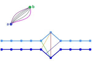
Fig. 25: Comparing geometric paths. (top) A set of homotopic paths. (bottom) The maximum error between 2 discrete paths, using 4 distance metrics.
This work investigates methods for comparing the similarity of a set of homotopic paths in geometric space. The paths have the same start and goal positions, but the route is different. Various metrics were compared, including: Cross-correlation, Epsilon / Perkal bands, Fréchet distance (min-max) and Hausdorff distance (max-min). These metrics were applied to the problems of planning the path of the mobile robot and cartesian path planning for a manipulator arm.
Biped Robots
Biped Walking using MPC
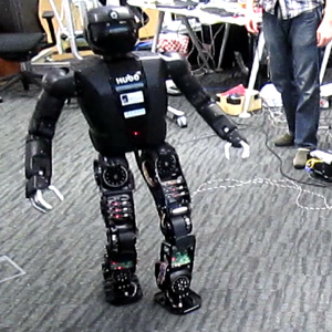
Fig. 26: Robot walking around the office.
Implementation and analysis of walking algorithms for a full-sized humanoid robot. A bottom-up approach for walking allows you to define the footstep positions first and then find a stable pose for the robot’s upper body. This allows the robot to execute a footstep plan to walk around or in-between obstacles. The problem is solved online using MPC (Model Predictive Control) to satisfy the ZMP stability criteria, with stabilization control at the ankles and hip using sensor feedback.
This work was undertaken at the University of Queensland and the A*STAR Institute for Infocomm Research.
Real-time Control System for Humanoid Robot
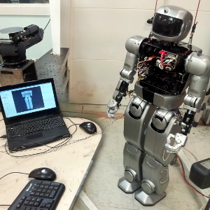
Fig. 27: The robot’s status displayed on ROS Rviz.
Development of a Linux-based control system for the HUBO humanoid robot, to replace the existing Windows-based software. The system uses a hard real-time core for accurate control of the robot’s joints. The core interfaces with ROS (Robot Operation System) to enable development of high-level algorithms and for improved collaboration between multiple research groups. This work became the basis for Team KAIST’s entry into the DARPA Robotics Challenge.
This work was undertaken at the Humanoid Robot Research Center at KAIST.
Other Research
Autonomous Underground Robots
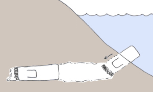
Fig. 28: Concept for an autonomous burrowing robot that is delivered by an underwater vehicle.
Unmanned Autonomous Systems (UAS) are currently used in the air, on the ground, and under the sea. However, one area of our world that is currently off-limits to autonomous robots is underneath it. The following page includes a literature review and concept design for an underground burrowing robot.
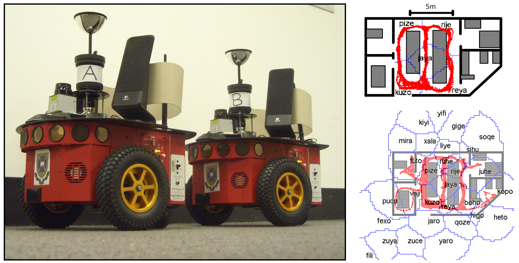
Fig. 29: Pioneer P3-DX mobile robots were used to test the language-learning system (left). The robots create a topological map, labeled with places they have been or not been (right).
To enable robots to work collaboratively with humans, and operate safely in our homes, they need to be able to communicate effectively with humans. One question is: should robots use human language, a more animal-like language, or create their own language?