Projects

Robot Camera Calibration

Fig. 1: Camera-to-gripper extrinsic calibration.

As part of various projects I’ve had to implement solutions for robot sensor calibration.
This includes intrinsic and extrinsic camera calibration, aligning multiple sensors co-located on a robot, or computing the offset between multiple sensors looking at the same scene.

Click here to read more

Assembling a Humanoid Robot & Repairs

Fig. 2: Partially assembled humanoid robots.

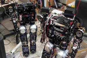
Assembling a full-size humanoid robot, including the aluminum frame, actuators, and routing all the wiring. Conducting repairs including testing and replacing electronic boards and Harmonic Drive reducers.

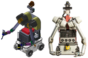
Upgrades to Mobile Manipulator Robot

Fig. 3: Proposed design and upgraded robot.

A trade study to upgrade the head, neck and mobile base of a robot called HERB at CMU. This included researching and comparing off-the-shelf products, developing design mock-ups and analyzing the expected capability of the improved system.

Click here to read more

Spinning LiDAR Mechanism

Fig. 4: LiDAR output displayed in ROS Rviz.

A proof-of-concept for a spinning LiDAR sensor using a Velodyne VLP-16. Typically a spinning LiDAR will incorporate one planar 2D sensor, either rotating on a horizontal axis or “knodding” up-and-down. In contrast, the goal of this experiment was to try rotating a multi-beam 3D sensor on a vertical axis. To the best of our knowledge this was the first attempt to construct a spinning LiDAR using the VLP-16.

Click here to read more

iServe – Robot Bartender

Fig. 5: Concept drawing for robot bartender.

A social robot that can pour you a drink. It is designed to provide a fun, interactive drinking experience that includes games and personalized service.

This was a team project with C. K. Jung, K. Oh and Y. Kim.

Social Robot for the Workplace

Fig. 6: Your friendly workplace robot.

People often work long hours at the research lab or office, sometimes late into the evening. However not everyone is lucky to have positive relationships in their workplace. This robot is designed to be a worker’s friend in the workplace, thereby improving their emotional well-being and indirectly improving their productivity.

This was a team project with K. Sung, T. Kim and J. Seo.

Bilateral Controller for Teleoperation

Fig. 7: Testing the tele-operated robot.

A force-feedback controller for a tele-robotics system that allows a person to remotely operate a robot arm with a sense of “touch”. This is useful for dexterous manipulation tasks, such as surgery, where it is important to know how hard you are pushing on something.

Click here to read more

This was a team project with C. K. Jung & T. J. Kim.

Working model of a Defense Satellite
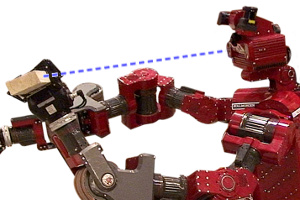
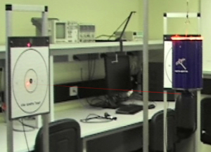
Fig. 8: The satellite fires a laser at the target.

This project was to design, build and demonstrate a single-axis working model of a space satellite, that can detect and mark targets using a low-power laser. The final design is a tightly-integrated mechatronic system for which the development required multidisciplinary knowledge of electronics, mechanical design and computer software.

The following page includes videos of the Satellite in action and a detailed description of the design and manufacturing process: Click here to read more

This was a team project undertaken in 2011 with S. Hinton, J. Jangam and K. Lawson.

Robot Localization using Omni-directional Camera

Fig. 9: Colored landmarks in the robotics lab.

A prototype localization system using colored poles as landmarks in the environment. The mobile robot has an omnidirectional camera, allowing it to capture an image of the entire environment. This makes the method robust to rotation and occlusions, compared to alternative approaches using only a forward-facing camera.

Click here to read more

Segmentation of Cardiac MRI using Active Contours

Fig. 10: Two active contours (shown in red) are attracted to the boundary of this cross sectional image of the left ventricle.

The goal of this project was to segment the left ventricle region of the human heart from MRI (Magnetic Resonance Images) and to compute the cross-sectional area. A Cardiologist can use this data to determine the efficiency of the patient’s heart. I implemented an active-contour (“snake”) method for segmentation. The user initialises the algorithm by clicking multiple points in the ventricle region of the first image. These control points are used to define a pair of thin-plate splines that automatically contract (or expand) until they hug the inner (or outer) wall of the ventricle contour.

Click here to view

3D Model Reconstruction using Shape from Silhouette

Fig. 11: The process to create a 3D model using multiple photos of an object.

A software program to build a 3D model (mesh file) of an object, using only a sequence 2D camera images. I used the “Hannover Dinosaur Sequence” dataset and a method called “shape from silhouette”, also known as “voxel carving”. The object is placed on a turntable and rotated, in order to capture each side of the object. Color-based segmentation is used to remove the background and extract the shape (outline) of the object from each angle. The method works well and produces good quality 3D models. The benefits of this method are that: (1) a camera is cheaper than a 3D sensor, and (2) for textureless or reflective objects, the result is much better compared to other methods.

Click here to view

Wildlife Surveillance System
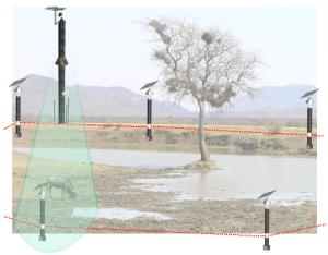
Fig. 12: The system detects a wild animal.

Scientists need to monitor and count wildlife in remote areas for conservation purposes. Similarly, farmers and land owners need to detect the presence of “feral” or invasive animals in order to develop a management plan. This project was the design of an electronic surveillance system for detecting and recognizing animals in remote areas.

Click here to read more

This was a team project undertaken in 2010 with M. Manitta, S. Otte, E. Peng and A. Chi.

Reverse-engineering of Snow Making System
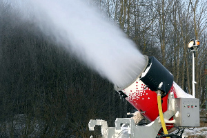
Fig. 13: A fan-gun producing artificial snow.

A ski resort had an aging snow-making system that was starting to have some reliability issues and was no longer supported by the manufacturer. Each fangun has a program written in assembly language, running on a 8051 Microcontroller with a UV-erasable memory chip. I was able to to reverse engineer the program, test the system’s behaviour and make some modifications.

Click here to read more

Pick-and-Place using Industrial Robot

Fig. 14: Robot grasping colored blocks.

I have developed various pick-and-place tasks using ABB and Yaskawa Motoman robots. This involved programming using proprietary languages RAPID and INFORM, or third-party software such as ROS.

Click here to view

Robot Arm Controller

Fig. 15: Old robot arm, missing a controller.

A multi-axis motion control system for a 5-DOF robot arm, programmed in python from a desktop PC. The real-time controller comprises an Atmel Microcontroller and six off-the-shelf Servo Drive modules.

Tracking & Control of Non-rigid Airship

Fig. 16: Testing the flying airship.

A system for vision-based tracking and autonomous control of a flying “blimp”. The airship is a helium filled balloon with two propellors. A ground station tracks the airship’s position using a pan-tilt camera.

Click here to read more

Mobile Robot using Dubins’ Path

Fig. 17: Mobile robot with embedded system.

A small mobile robot capable of driving a programmed path, using “dead reckoning” and a combination of straight lines and curves. The robot’s “brain” comprises an Atmel Microcontroller and an Altera PLD (Programmable Logic Device).

Click here to read more

This was a team project with C. K. Jung & T. J. Kim.

8-bit Microcontroller on an FPGA

Fig. 18: FPGA board and timing simulation.

A complete 8-bit Microcontroller constructed from individual logic gates and implemented on an FPGA (Field Programmable Gate Array) chip. The architecture includes a Control Unit, Arithmetic Logic Unit, Instruction Fetcher and a Memory Controller. It supports a small Instruction Set based on Atmel and RISC, where each instruction cycle takes 4 or 5 clocks. The design was synthesized in VHDL using Xilinx ISE, analysed and tested in simulation, then implemented on a Xilinx Spartan3E Development Board.

Click here to view

Fastenerless Bracket for RGB-D Sensor

Fig. 19: CAD model of sensor bracket (yellow).

This allows you to attach an ASUS Xtion 3D depth sensor to the head of a REEM robot.
This robot is sleek and well-designed, but there are no mounting holes on the upper-body for mounting additional sensors. The bracket is curved to match the shape of the robot’s head, with four arms that hook underneath a groove on the head. There are some additional threaded holes for attachments and clips to hold the sensor’s cable in-place. The bracket was manufactured in nylon using FDM (Fused Deposition Modeling).

Click here to view

CAD Drawing

Fig. 20: Various CAD drawings and models.

Engineering design work involves generating 2D mechanical drawings or 3D modelling, so I have lots of experience using AutoCAD, SolidWorks and Inventor. I have produced designs for manufacture using CNC machine, hand-operated mill, lathe, bending sheet metal and rapid-prototyping using 3D printing.

This includes: robot arms, robot system assemblies, robot grippers, end effectors, wiring diagrams, gearbox cover, valve body, hydraulic pump, machine vice, fan blades, ratchet, custom Lego parts, and various adapters, sleeves, brackets, jigs, fittings, plates, gaskets, spindles, shafts and pulleys!

Click here to see more

4-DOF Robot Arm with Visual Servoing

Fig. 21: Robot arm with camera on end-effector.

This 4-DOF robot arm uses image-based visual servo control to track the position of a colored object. The robot is controlled from a laptop computer via USB, and the algorithm was implemented in C++ and OpenCV.

Grid-Map Exploring Mobile Robot

Fig. 22: The robot explores and maps the grid.

An autonomous mobile robot capable of exploring a world comprising of a grid of colored squares and block-shaped obstacles. The robot has a color sensor and ultrasonic range-finder.

Click here to read more

RoboCup Rescue

Fig. 23: Robot lifting the “victim” to safety.

A robotics demonstration to advertise the RoboCup Rescue competition and encourage students to study robotics. The robot is a mobile manipulator, capable of grasping objects using its arm and moving them to a different location.

Click here to read more

Balloon-bursting Robot

Fig. 24: Robot with 6 sharp pins to pop balloons.

This robot can seek-and-destroy inflatable party balloons. In the photo you can see the arm is in the “down” position, with a collection of sharp spikes to pop the balloon. The robot finds a balloon using an ultrasonic distance measuring sensor (range finder) and checks the color using a color sensor. Then the motor is activated to quickly swing down the arm and burst the balloon.

Click here to view

Line-following Robot

Fig. 25: Robot following a line.

This robot uses I.R. (Infra-Red) sensors to follow a black line on a white-colored sheet. The base is a Tamiya dual motor gearbox, which makes it easy to build a differential drive robot. The axle is located toward the rear-end of the robot with an old red LED at the front for skid steering. There are 3 I.R. Emitter-Receiver pairs across the front that help the robot navigate sharp turns, T-junctions and line endings. The robot has an Atmel ATmega8 8-bit Microcontroller, programmed in C language. The second smaller chip is a SN754410 H-Bridge motor driver. There are some extra LEDs and a buzzer on the board, just for fun.

Click here to view

Line-following Robot (Lego Mindstorms)

Fig. 26: Line following robot made from Lego.

Throughout my studies I have constructed numerous line-following robots using Lego. It seems like a simple task but there are subtleties in the design, depending on the number of sensors used, how the sensors are located, and the algorithm behavior. These all have trade-offs that affect the system performance. The particular challenge shown here was to make the fastest line-following robot using only one RGB color sensor.

Click here to view

Wire Loop Following Robot

Fig. 27: Robot following a buried wire.

This robot detects and follows an electrical wire, similar to an AGV (Automatic Guided Vehicle) in a factory. The inductive loop is powered by a signal generator and amplifier circuit. Underneath the robot’s base are two wound copper coils that are connected to dual signal detection circuits. The detected signal differential is used to set the voltage applied to each drive motor.

Click here to view

“Trash can” Mobile Robot

Fig. 28: Design drawing and robot prototype.

A robot made out of a rubbish bin (trash can), inspired by fictional robots like R2-D2. It’s a differential-drive mobile robot with an on-board Intel x86 computer. It could be remotely controlled or follow a programmed path, however it had no sensing capabilities.

Click here to read more

Mobile Manipulator Robot

Fig. 29: Mobile manipulator driving on table.

I constructed this robot based on plans from a book. The base is hardwood with two drive motors and plastic skids. The arm has 1-DOF (up/down) and is made from balsa wood. The gripper is actuated via a cable and there’s a touch-pressure sensor in the gripper jaws. The unpainted box contains a light sensor (LDR) in a dark tube. There’s a relay board inside the robot. Power and I/O signals are received via a ribbon cable from an external computer. This robot could pickup lightweight objects via remote control or drive along a pre-programmed path using dead-reckoning.

Click here to view

Vintage Computers & Robots

Fig. 30: Repairing Apple Macintosh computers.

As a hobby I enjoy restoring vintage computers and robots, such as the early Microcomputers produced by Atari, Apple, the BBC (British Broadcasting Corporation) and Heathkit. The diodes and capacitors often deteriorate with age, so they need to be replaced. And it can be tricky to get software running that used to be distributed on disk or cassette because these magnetic storage devices also deteriorate.

Click here to view

TI Calculator Hacks

Fig. 31: Graphics calculator modified with IO port.

When I was in school I distributed software and developed hardware modifications for the TI (Texas Instruments) Scientific Graphing Calculators:

  • Custom 10-pin I/O port for external devices. Provides power, clock signal and serial data port. Automatically activated when you plug-in the accessory.
  • External speaker. Connects to the 10-pin I/O port. The box contains a small amplifier and volume control.
  • Adapters to convert the 3-pin data transfer cable to serial or parallel port on your PC.

Most high-end calculators include a USB port to transfer software programs, however the serial port is useful if you want to control other devices in real-time.

Click here to view

Electrical Projects

Fig. 32: Distribution panel for voice and cable TV.
  • Structured wiring systems at our house and office. This provides a network for internet, audio, voice, security and automation devices.
  • Power distribution, charging systems and temperature control for camping trailer, RV (Recreational Vehicle) and automotive.
  • Outdoor garden lights for the Christmas holiday season, including Santa Claus and his reindeer on the roof.

Click here to see more

Electronics Projects

Fig. 33: Various electronics projects.

I enjoy building electronic projects, including soldering through-hole and SMD (Surface Mount) components. I have experience making PCBs (Printed Circuit Boards) and prototypes on soldered strip-board and solderless breadboard.

Some of my projects include:
Computer I/O interfaces, Microcontroller boards, H-Bridge Motor Controllers, Power Regulators, AM/FM Radio, Door Chime, Frequency Meter, Guitar Effects Pedals, Lighting Controllers, Strobe Light, Security Alarm, Stereo Amplifier, Wireless Microphone, Counters, Timers and Games.

Click here to view