As part of various projects I’ve had to implement solutions for intrinsic and extrinsic calibration, including:
- Camera intrinsic and extrinsic parameters (focal length, distortion)
- Camera to 2D sensor (another camera)
- Camera to 3D sensor (depth, lidar)
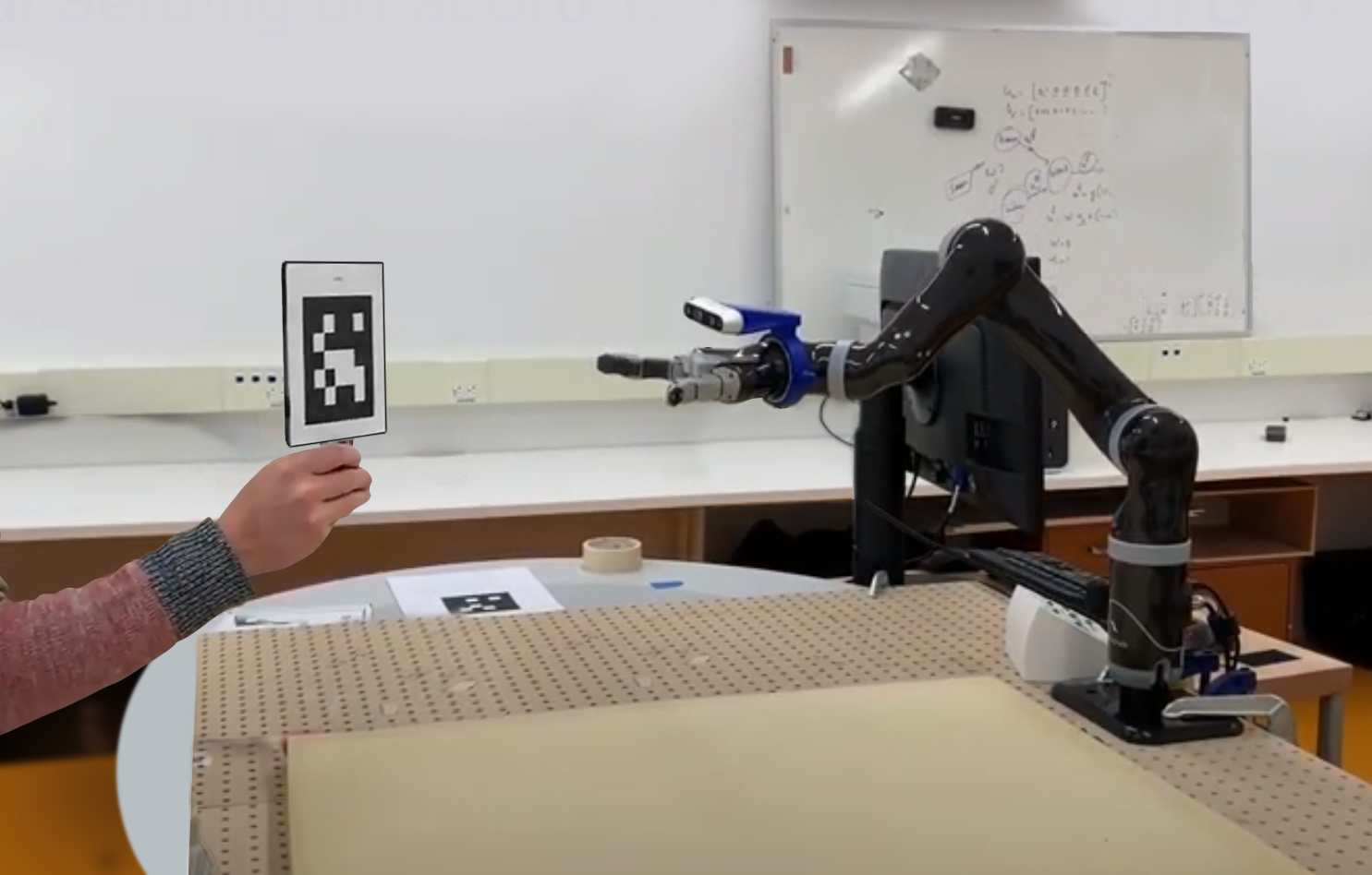
- Camera-to-Robot (mobile base, manipulator arm)
Sometimes you can assemble the robot, calibrate everything once, and then the sensor offset transforms remain constant for an extended period. However if you frequently change sensors or swap the end-effector then automatic calibration is a better solution, allowing the robot to find the parameters by itself.
This page has some selected diagrams and photos related to my work on calibration.
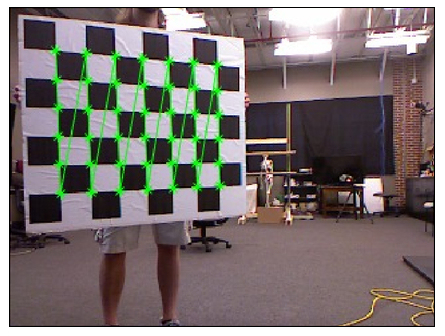 checkerboard (chessboard pattern). |
 parameters. The robot is programmed to move in a sequence of configurations. |
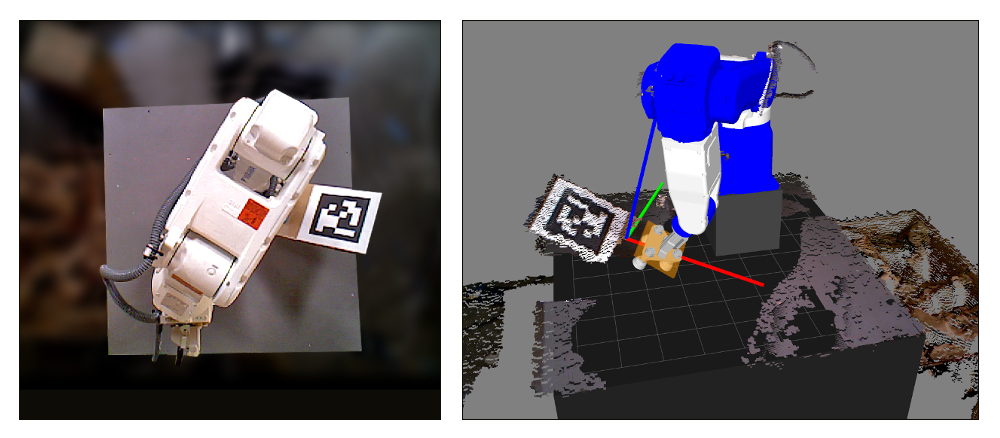
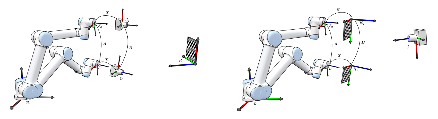 comparing sensor-in-hand (left) Vs. an external fixed sensor (right) [1]. |
 such that two planar faces are visible, providing a constraint for calibration. |
 a depth sensor fixed to the wrist. |
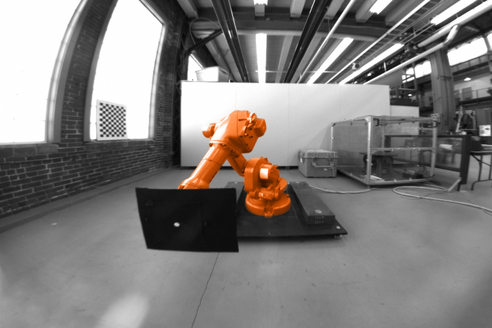
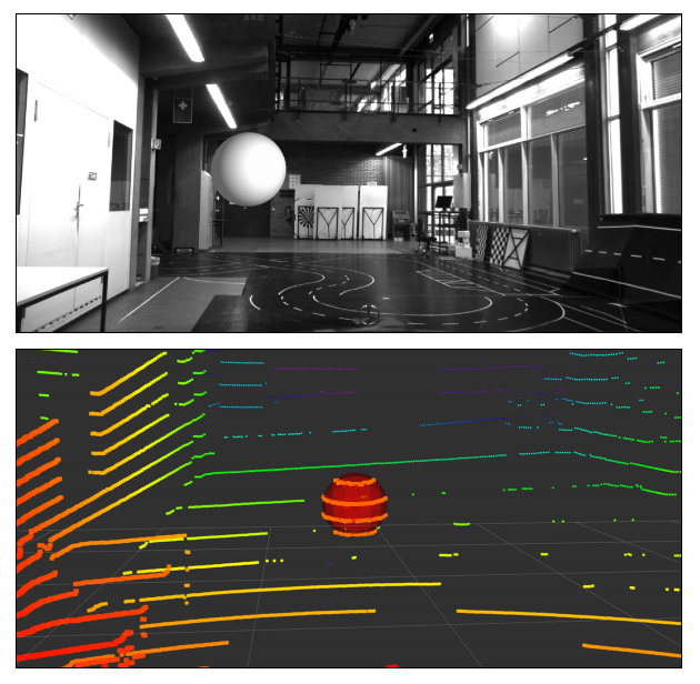
 calibration of a downward-facing depth sensor. |
 multiple depth sensors looking at a scene. |
 using checkerboard (chessboard pattern) and planar surface. |
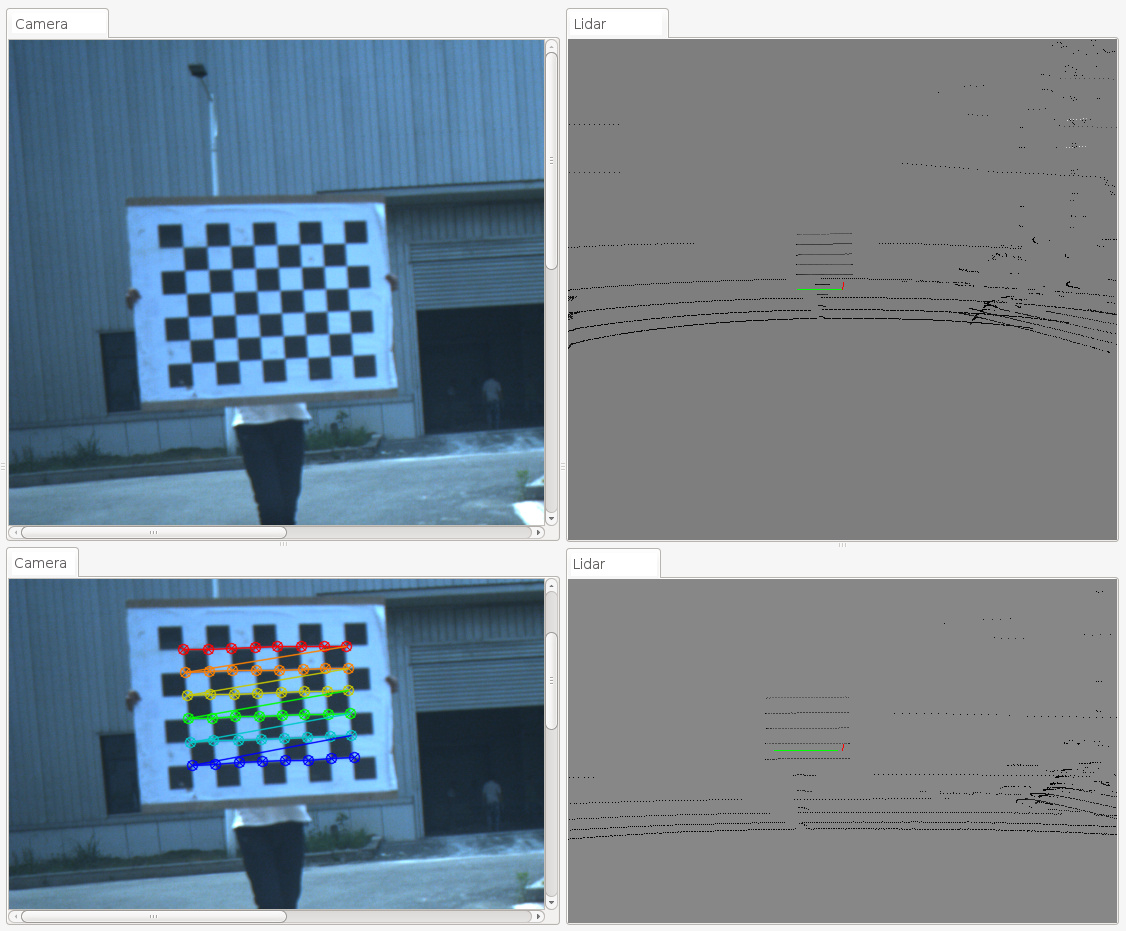
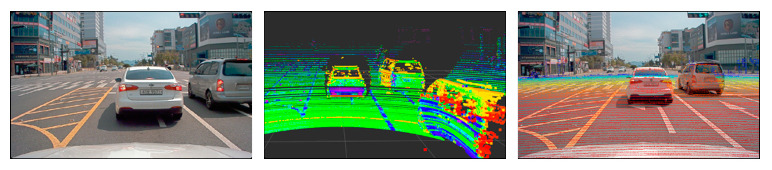 pipeline. This shows the LiDAR beams overlaid on top of a camera image [2]. |
.
|
[1] Diagrams by T. A. Myhre
www.torsteinmyhre.name/robcam_calibration |
|
|
[2] Figure adapted from:
G. A. Kumar, J-H Lee, J. Hwang, J. Park, S. H. Youn and S. Kwon, “LiDAR and Camera Fusion Approach for Object Distance Estimation in Self-Driving Vehicles”, MDPI Symmetry, February 2020. |