This project describes the design of a system for monitoring biodiversity in remote areas. It is an electronic surveillance system that uses cameras to capture images of ground-dwelling mammals, combined with software to count and classify them. You can find a full PDF report below.
The system was proposed to EWB (Engineers Without Borders) in 2010, who were representing a community group called the Kooma Traditional Owners [1]. The group operate a property in a remote area of south-west Queensland in Australia and they wish to develop an economically and environmentally sustainable ecotourism business. However the land has a significant problem with “feral” or invasive animals. Installing this wildlife monitoring system would help the group to design and carry out a suitable management plan for the property.
Previous work
Extensive research was conducted into existing electronic methods for monitoring wildlife. This identified many useful technologies, such as Machine Vision Software (Fig. 2-3), Camera Traps (Fig. 4-5) and Wireless Sensor Networks. Various sensor types were also investigated, to determine which would be most effective and reliable for detecting the presence of animals.
|
Fig. 2:
Animal recognition system: Animals are herded in front of a “blue screen” with a machine vision camera. 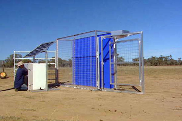 ABC Landline 2008 |
Fig. 3:
Animal recognition system: A silhouette image is created using an edge detector, which is then passed to an image classifier [2]. 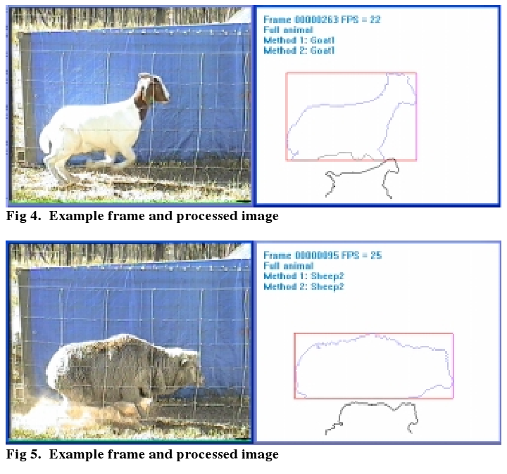 M. Dunn, J. Billingsley & N. Finch, 2003 |
Fig. 4:
Setup of a movement-triggered remote monitoring camera, with a separate IR (Infra-Red) illumination light [3]. 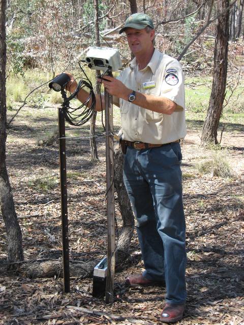 Department of Territory and Municipal Services, 2010 |
|
Fig. 5:
A commercially available Infrared-triggered Camera called a “Trail Cam” [4]. 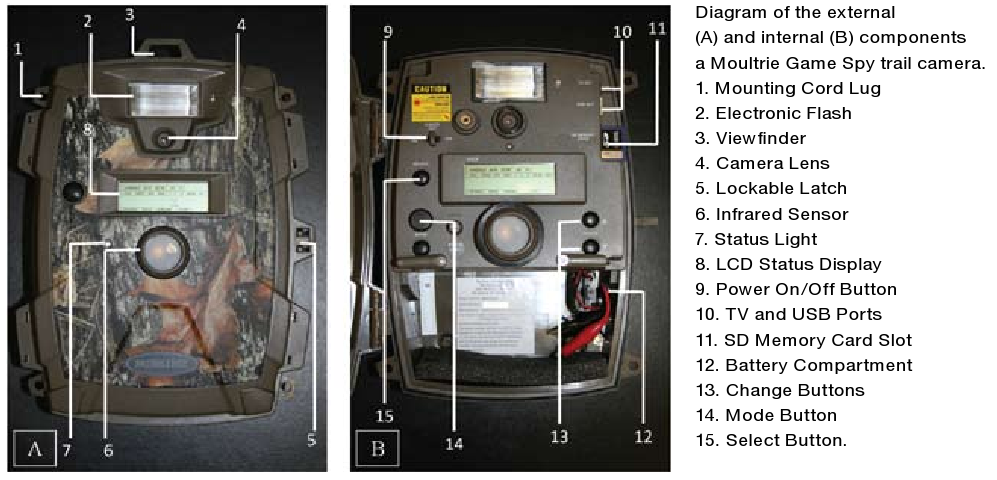 Dreibelbis et al., 2009 |
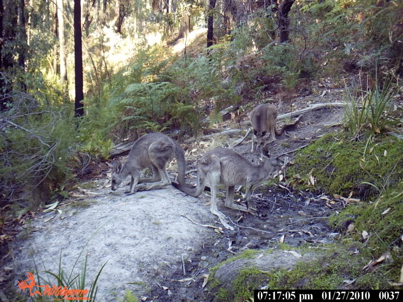
Fig. 6:
A mob of Eastern Grey Kangaroos, as captured by a “Trail Cam”. |
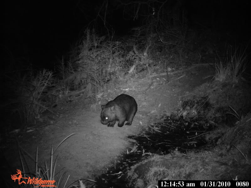
Fig. 7:
An infra-red light makes it easy to see this nocturnal Wombat at night time. |
Proposed design
Four concept designs were developed:
- PIR sensor-triggered Camera Trap (Fig. 8)
- Webcam with Laptop & local image processing (Fig. 9)
- Virtual Laser Beam “Fence” with pole-mounted Pan/Tilt Camera (Fig. 10)
- Wireless Sensor Network of PIR-triggered Cameras (Fig. 11)
|
Fig. 8:
Concept Idea #1: A PIR sensor-triggered Camera Trap. 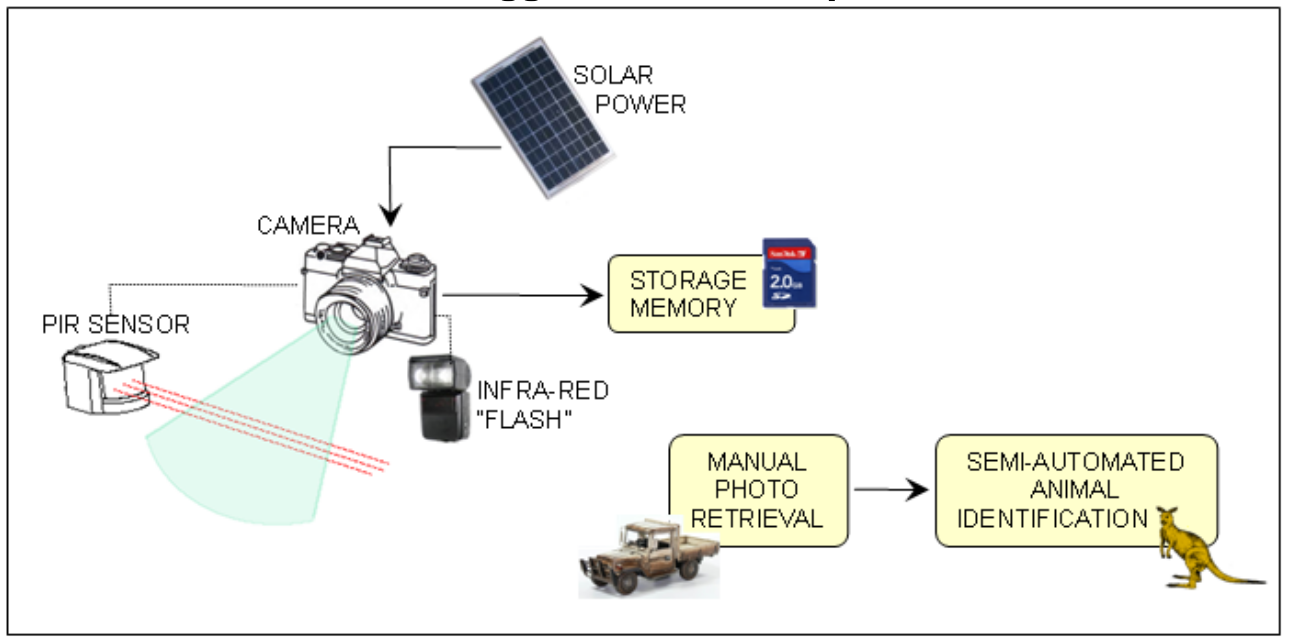 |
Fig. 9:
Concept Idea #2: Web-cam with Laptop and local image-processing. 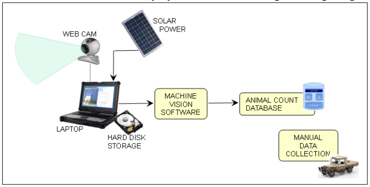 |
|
|
Fig. 10:
Concept Idea #3: Virtual Laser Beam “Fence” with pole-mounted Pan/Tilt Camera. 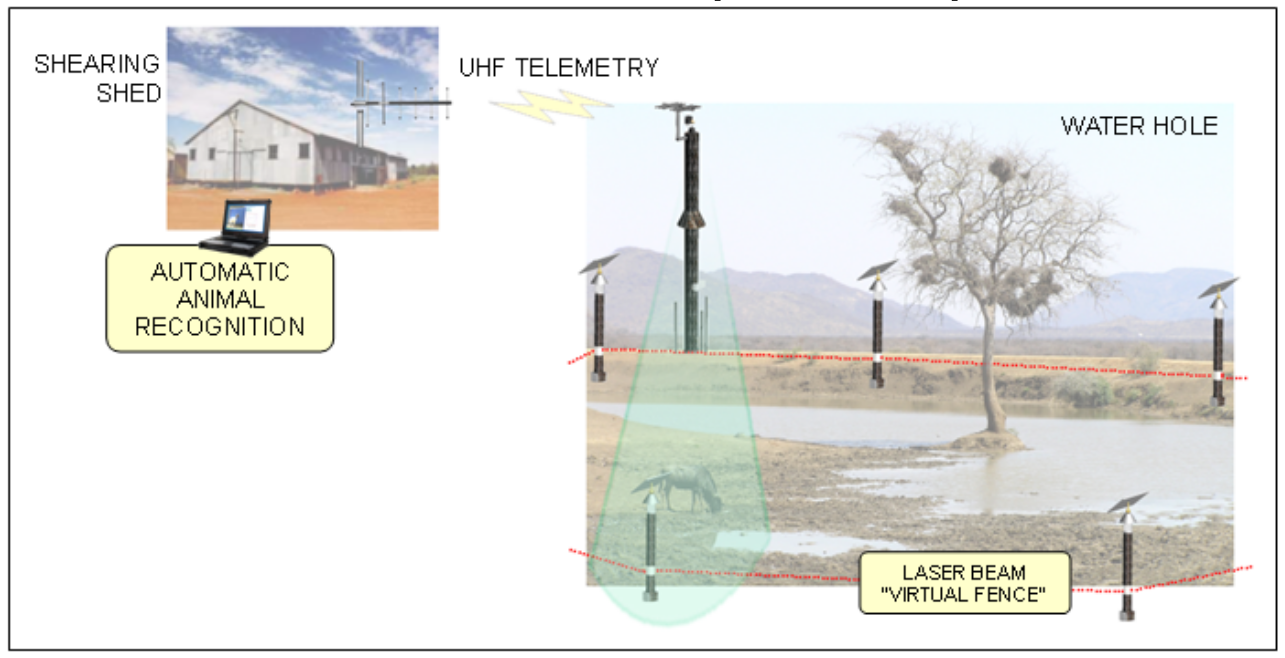 |
Fig. 11:
Concept Idea #4: Wireless Sensor Network of PIR-triggered Cameras. 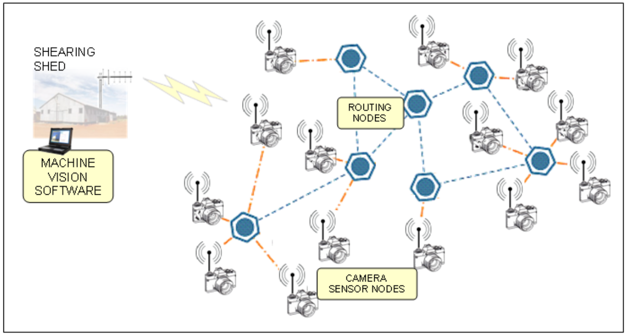 |
The most feasible design, ranked against the criteria described in our report, was the Virtual Laser Beam Fence with Pan/Tilt Camera.
The final design costs of:
- “Laser Beam Fence” comprising between 2 to 7 Laser Beam Sensor Posts per location
- One pole-mounted Pan/Tilt Camera per location
- Radio Telemetry data link to Base Station
- Base Station with Laptop running Object Recognition Software
- Optional Portable Radio Repeaters
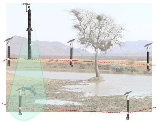
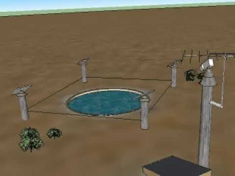
The system is flexible, and can be installed in a variety of locations. When an animal breaks the “electronic fence” (laser beam) the Sensor Post sends a signal to the Camera Pole which instantly turns to the appropriate direction vector of the trigger. The camera takes a digital photo and transmits it via RF telemetry to a Laptop PC at the Base Station where it is automatically processed by Animal Recognition software (Fig. 12).
|
Fig. 12:
Final design for a Virtual Laser Beam “Fence” with pole-mounted Pan/Tilt Camera. 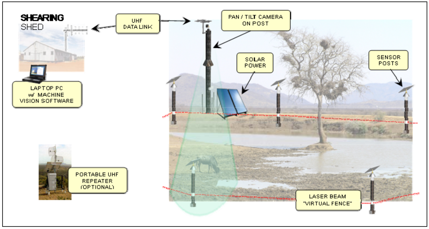 |
Design Drawings
The following drawings show the final design of the two primary components. The camera post is much taller and has the pan/tilt camera and solar panel mounted at the top (Fig. 13). Each of the sensor posts also has a small solar panel (Fig. 14).
|
Fig. 13:
Mechanical drawing of the pole-mounted pan/tilt camera. 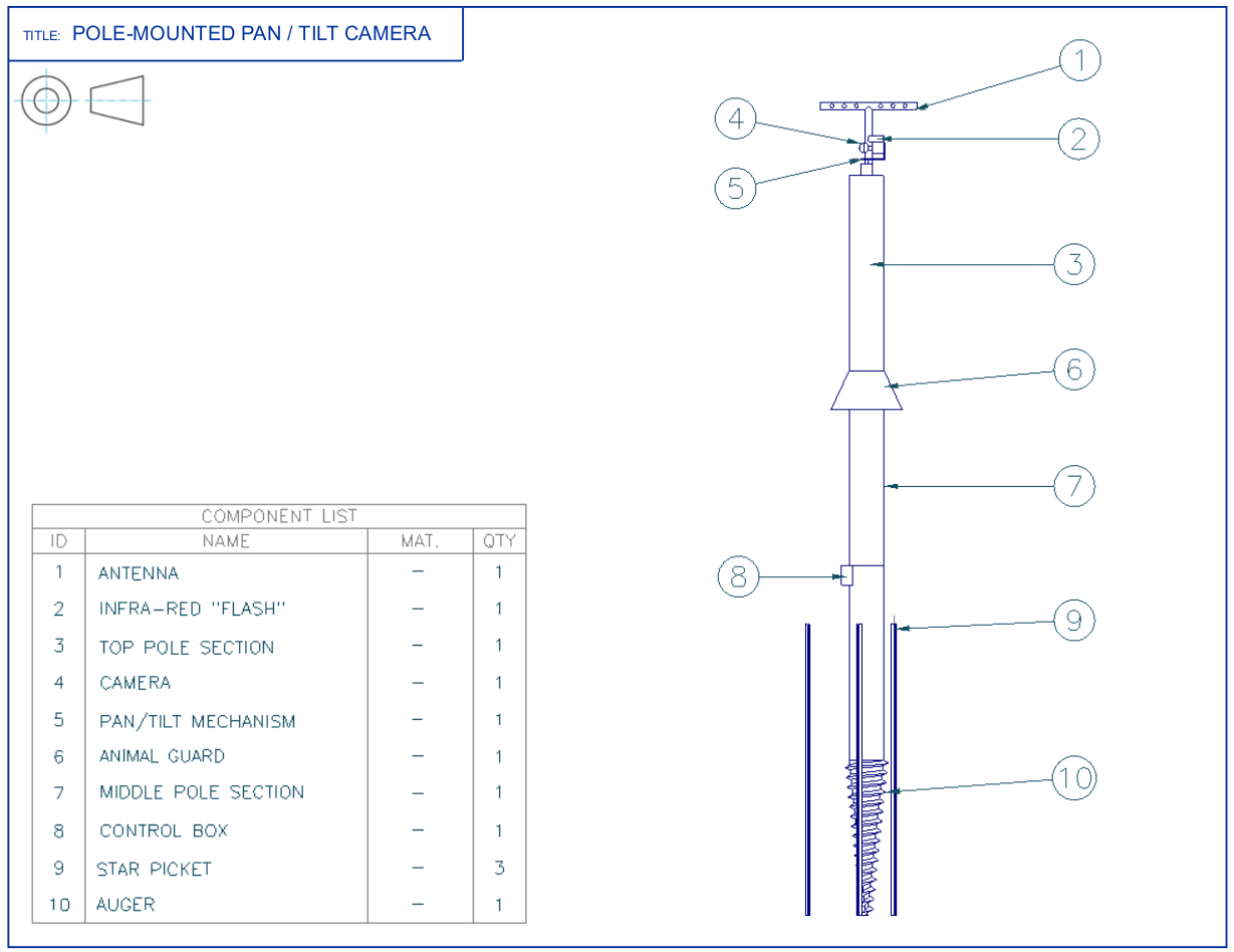 |
Fig. 14:
Mechanical drawing of the laser beam sensor post. 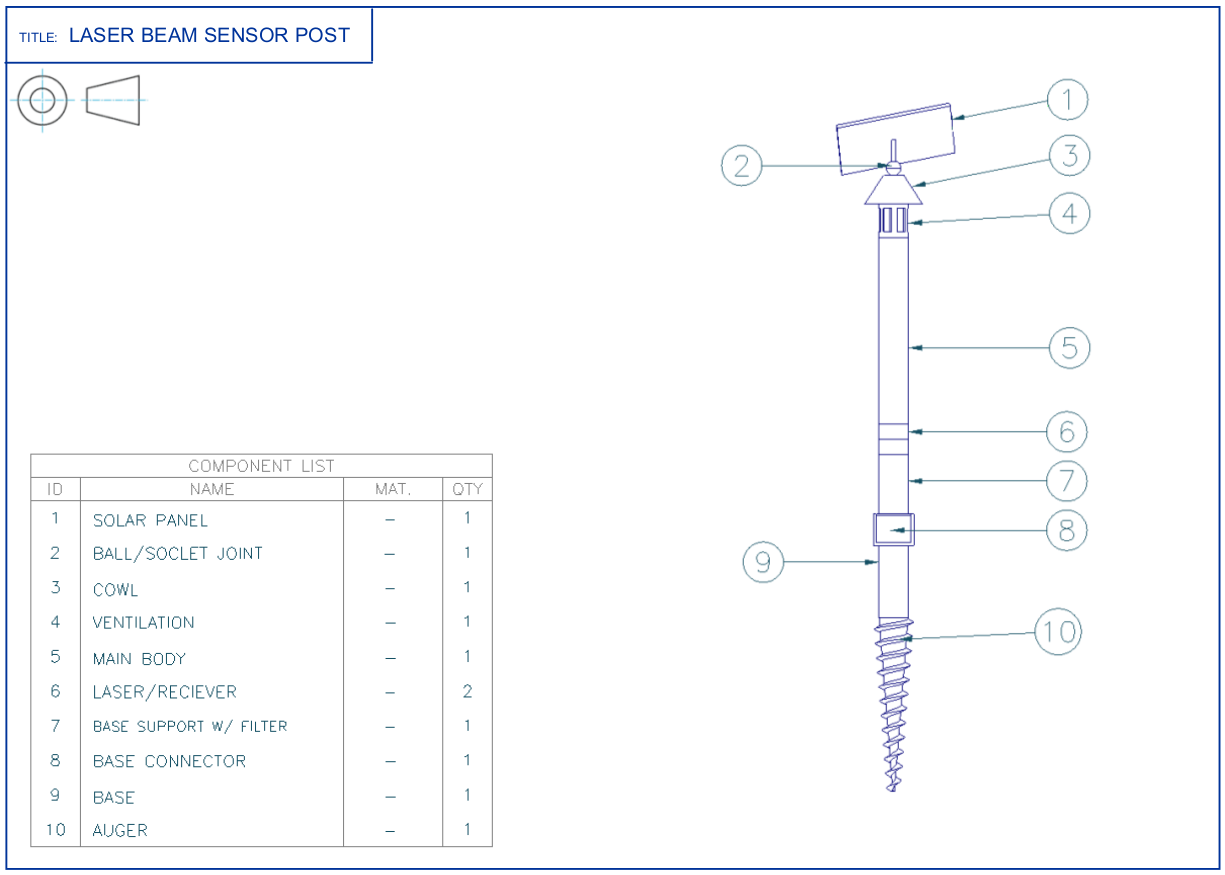 |
|
|
Fig. 15:
Block diagram of the system components. 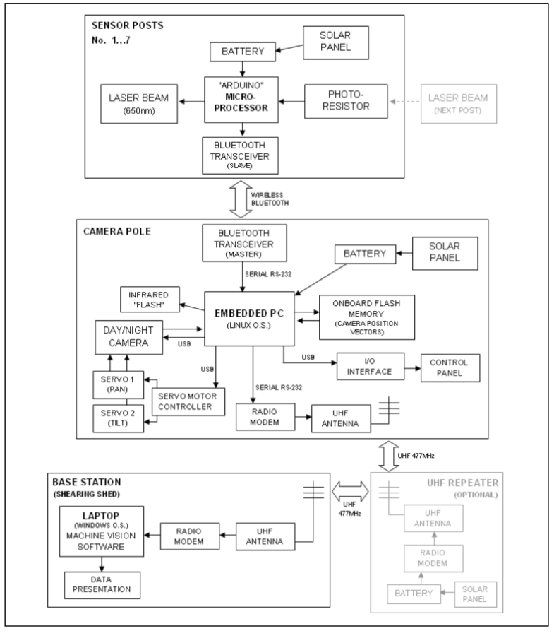 |
Fig. 16:
3D rendering of the pole-mounted camera and laser-based sensor. 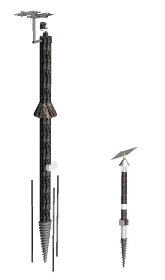 |
Video: |
Prototype
A life-size physical model of one sensor post is shown below (without the solar panel). The post is designed to screw into the ground. The laser beam transmitter and sensing modules can be independently rotated to align with the opposing post they are pointing at. There are vents at the top and bottom to allow airflow through the tube to cool the internal electronics, and a rain cover on top.
|
Fig. 17:
Physical model of the sensor post. 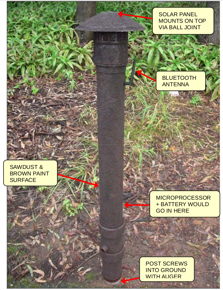 |
Fig. 18:
Close-up view. 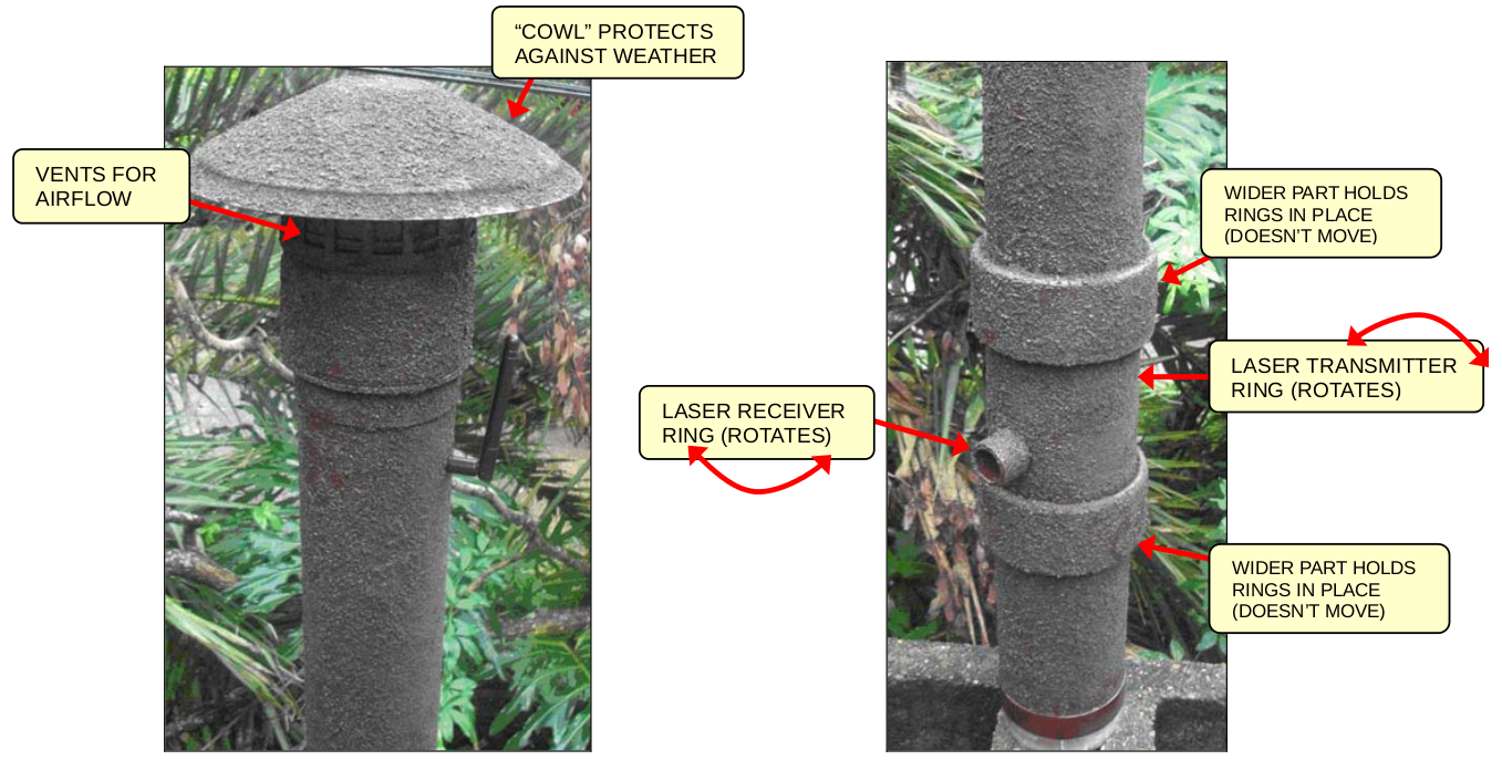 |
This project was undertaken at the University of Queensland in 2010 with M. Manitta, S. Otte, E. Peng and A. Chi
and was selected from hundreds of proposals to be a finalist in the 2010 EWB Challenge.
Report:

D. Butterworth, M. Manitta, S. Otte, E. Peng and A. Chi, “An Innovative and Versatile Wildlife Surveillance System – A conceptual design for a remote community in Outback Queensland”, un-published, 2010.
PDF
|
|
|
|
[2] M. Dunn, J. Billingsley and N. Finch, “Machine Vision Classification of Animals”, in Mechatronics and Machine Vision 2003: Future Trends, Research Studies Press Ltd, Baldock, 2003, pp. 157-163
|
|
|
[3] Department of Territory and Municipal Services, Feral Animal Control Program, ACT (Australian Capital Territory), 2010.
|
|
|
[4] J. Dreibelbis, S. Locke, J. Cathey and B. Collier, “Potential Uses for Trail Cameras in Wildlife Management”, Texas A&M Institute of Renewable Natural Resources, Texas, 2009. PDF
|