One approach is to design tools specifically for use by a robot. Currently industrial robots can swap between multiple tools or end-effectors using a custom-designed tool changer mechanism. A more interesting challenge is enabling robots to use tools designed for humans. This means a human and robot could share the same workspace and tools, to collaboratively complete a task.
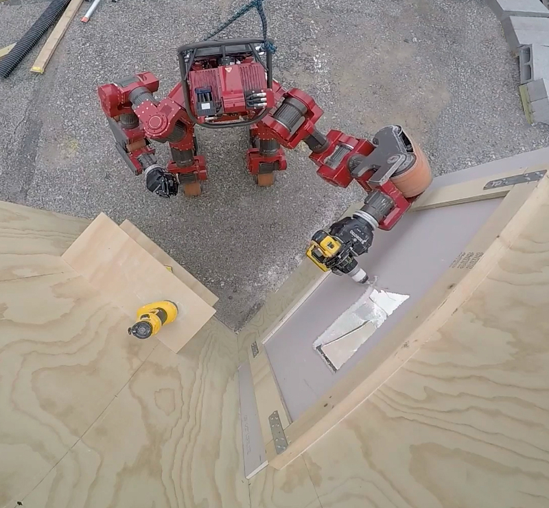
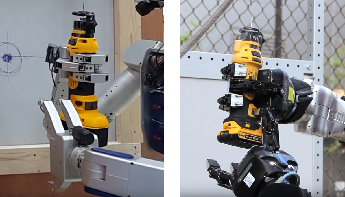
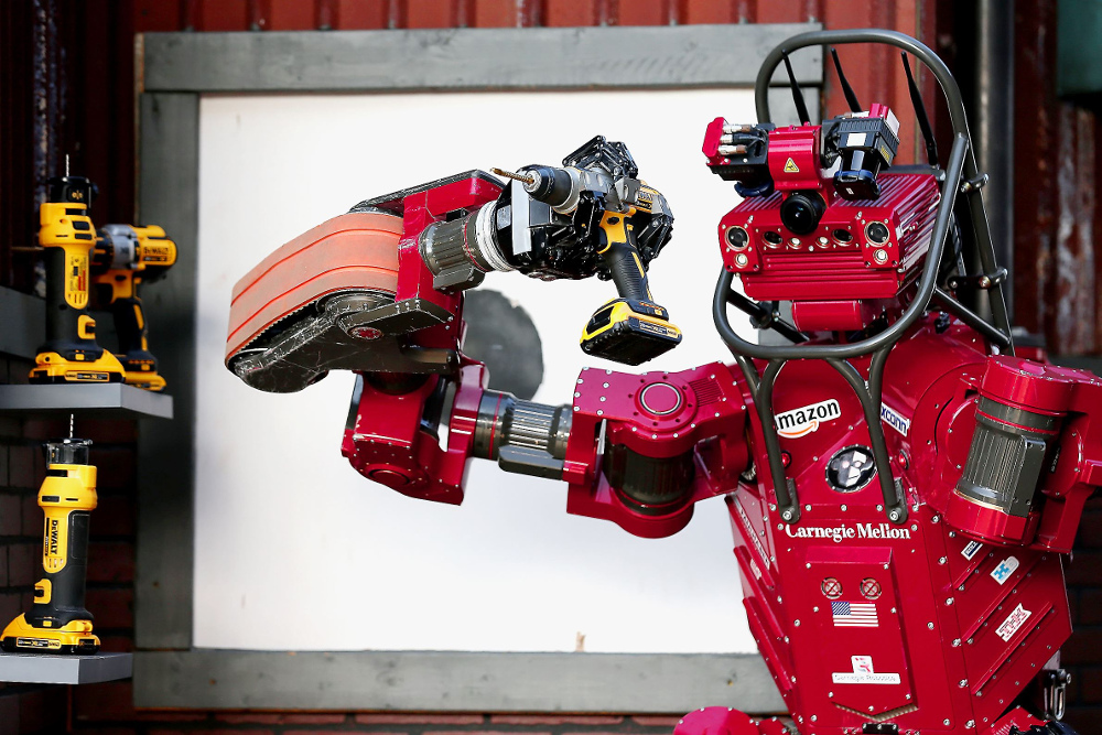
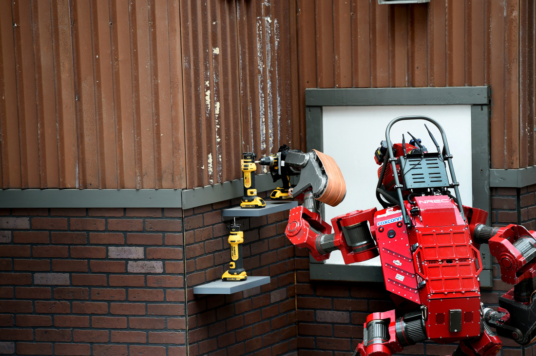
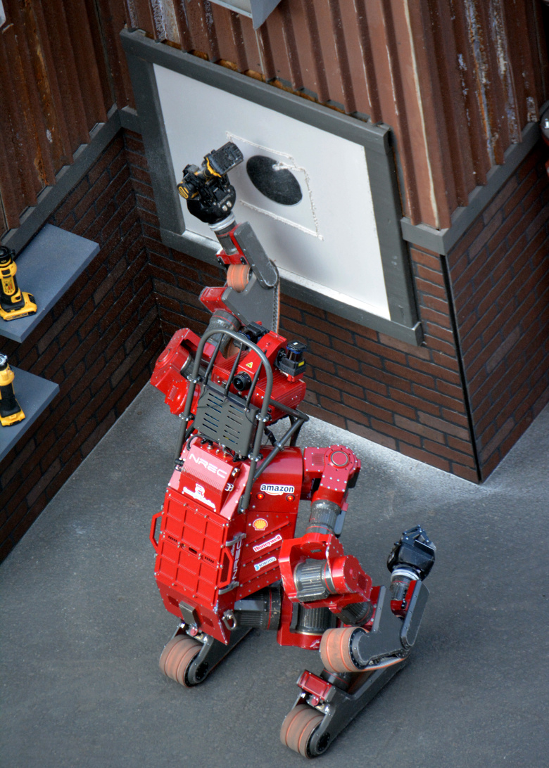
In the DARPA Robotics Challenge the goal was to develop a robot that could enter a hazardous environment and use any vehicles or tools that were available on-site. We developed a semi-autonomous system that enables the robot to use a cutting tool to cut a hole in a drywall panel (Fig. 1). This report describes the development of software algorithms for perception and dexterous manipulation using the robot CHIMP (CMU Highly Intelligent Mobile Platform) [1].
Related Work:
DARPA funded the ARM (Autonomous Robotic Manipulation) research program in 2010 to build a dual-arm robot and develop new capabilities in object manipulation [3]. The goal was that a human would only provide high-level instructions and the robot would autonomously perform tasks such as inspecting the inside of a gym bag or disarming an IED. Similar to Robonaut, the robot was physically capable of performing these tasks but only when remotely controlled by a human. Ultimately the ARM-S robot demonstrated autonomous use of tools, including turning on a flashlight, drilling a hole with a cordless drill, and installing a small tire and lug nuts.
Wall-cutting Task:
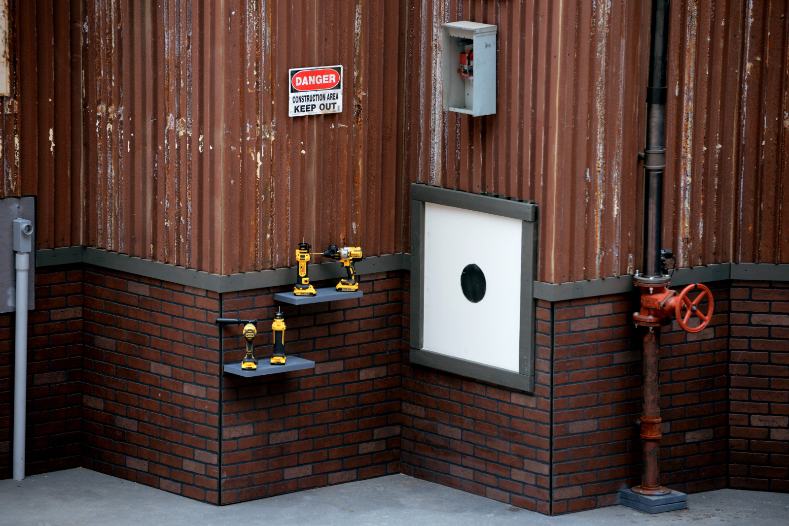
(left) Some cordless tools sit ready on the shelf. There is a cut-out tool and a drill.
(right) A sheet of drywall (white) is installed in a frame on the wall.
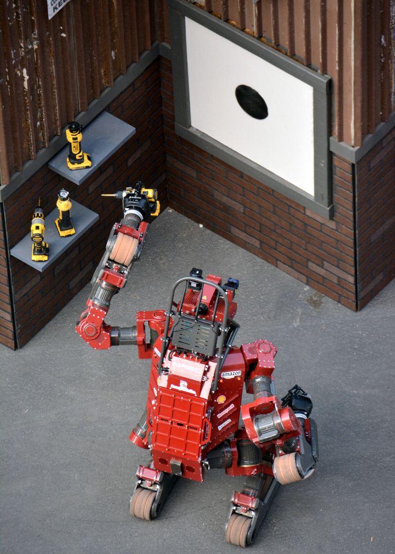
The task was to use a standard power tool to cut a hole 8″ (20 cm) diameter in a sheet of drywall, also known as gypsum, sheetrock or plasterboard. The minimum hole size was marked by a black circle on a drywall panel (Fig. 2).
Originally the dream was to make the robot break concrete or smash through a wall. However, supporting and manipulating a rock hammer or reciprocating saw (“Sawzall”) requires using two hands, and a combination of strength and dexterity that is challenging for a robot. In contrast, a cordless cut-out tool can be held with one hand and easily cuts through drywall.
For a mobile manipulator to complete this task, the following steps are required:
- Identify the tool and wall.
- Determine optimal location for the robot’s base (to pick-up the tool).
- Move robot.
- Detect pose of the tool, relative to the robot base.
- Grasp the tool.
- Move robot backwards from shelf.
- Check if it’s possible to activate the tool.
- Squeeze trigger and release.
- Check motor is turning or light is on.
- If can’t actuate trigger, operator chooses next action.
- Determine optimal location for the robot’s base (to cut hole).
- Move robot.
- Compute motion plan to cut hole in wall.
- Squeeze the tool trigger.
- Cut hole in wall.
- Monitor that cutting bit is following the path.
- If not following path, operator chooses next action.
- Check that cut was successful.
- If not, operator chooses next action.
- Move robot backwards from wall.
- Discard the tool.
The robot’s software system uses the concept of supervised [4] or shared autonomy [5, 6], whereby control authority is swapped back-and-forth between a human operator and the robot. A sequence of sub-tasks is encoded into an autonomous Agent, implemented using a state machine. The robot will autonomously perform one or more actions, and then stop and wait for input from the operator when required. After the operator makes a decision, the robot continues in autonomous mode.
Robot Platform:
The robot has two 7-DOF position-controlled arms with good repeatability sufficient for grasping. However, each joint has a torque-tube and clutch on the output shaft that can affect the arm’s calibration.
Various grippers and robot hands were considered:
- 3-finger Barrett Hand (used in the DARPA ARM-S program).
- 3-finger Robotiq Adaptive Gripper.
as well as prototypes developed during the DARPA ARM-H program:
- 3-finger hand by iRobot, Harvard and Yale.
- 4-finger hand by SRI, Stanford and MEKA Robotics.
- 4-finger hand by Sandia National Lab.
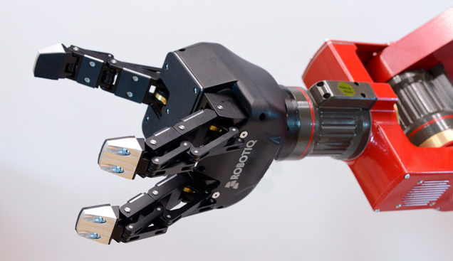
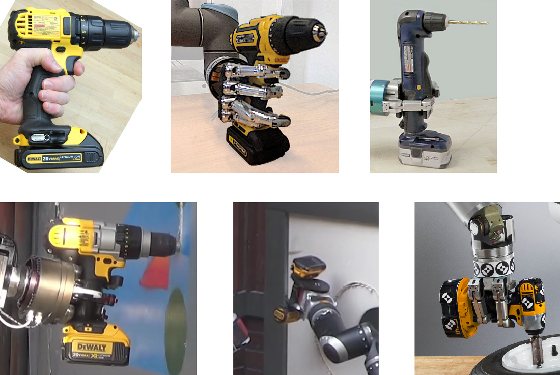
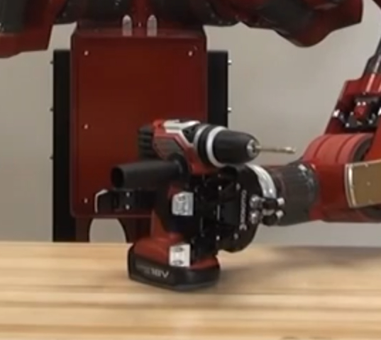
The Robotiq 3-Finger Adaptive Gripper (Fig. 3) was chosen because it is the most robust multi-finger hand that was available. It is made of aluminum and each finger is actuated using internal gears. The gripper was modified for increased durability, including tougher gears and re-routing the wiring through the wrist-center. One limitation of the 3-finger design is that the gripper can’t perform a 2-finger “precision” grasp or a 4-finger “power-cylindrical” grasp, which are useful for grasping objects like a hose or plug.
An anthromorphic hand has more dexterity for manipulation tasks like squeezing a drill trigger, however the mechanical design is less-robust. Typically each finger is actuated by a string or wire cable, with a second cable or spring for the opposing motion. During experiments we found these finger cables would often break and it is tedious to replace and re-tension them.
The Robotiq gripper is attached to each of CHIMP’s arms via a Barrett 6-axis Force/Torque Sensor. The F/T sensor uses a proprietary CAN Bus protocol that is different to the CANOpen protocol used by the robot’s motor controllers, however both protocols use a standard 11-bit CAN message ID and therefore worked correctly on the same 2-wire bus.
Tools:
To make it easier to solve the perception and manipulation problem, a specific product model for each type of tool was selected (Table 1).
When using a tool, you need to turn it on and use some method to verify that its operating (Table 2).
| Tool type | Model | Cutting bit | Speed | Trigger | Notes |
| Demolition hammer | Milwaukee 5337-21 Bosch 11255VSR |
Chisel | ● Robot could not manipulate tool. | ||
| Sawzall / Reciprocating saw |
Milwaukee 6538-21 DeWalt DW310 |
Saw blade | ● Robot could not manipulate tool. | ||
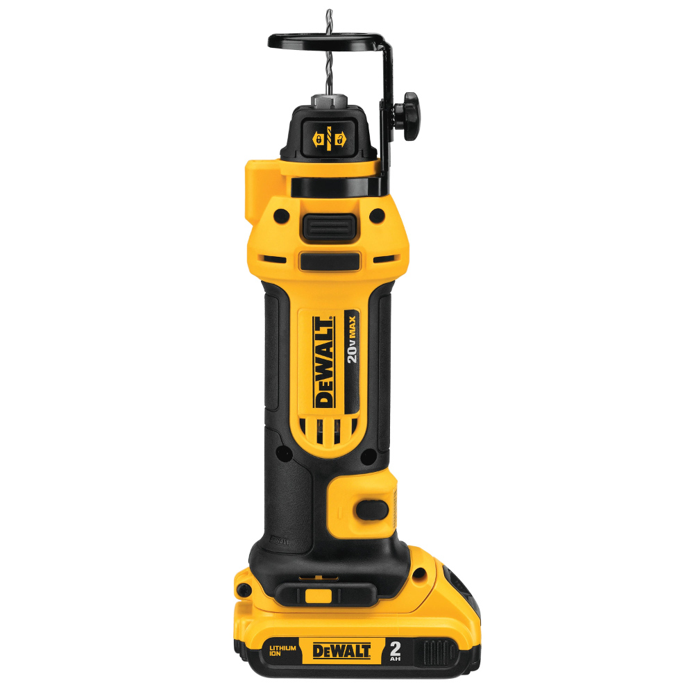
| Cut-out tool / Rotary spiral saw |
DeWalt DC550 KA | DeWalt DW6603 1/8″ drywall bit |
26000 RPM | Press button on or off |
● Used at DRC Trials in 2013. |
| Cut-out tool / Rotary spiral saw |
DeWalt DCS551 D2 | DeWalt DW6603 1/8″ drywall bit |
26000 RPM | Press button on or off |
● Used at DARPA Testbed and DRC Finals in 2015. |
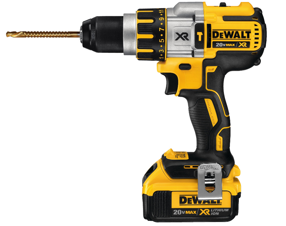
| Driver / Power Drill |
DeWalt DCD980 L2 | Morris 13042 5/16″ saw drill bit |
Variable 3-speed, max 2000 RPM |
Squeeze trigger fully | ● Used at DRC Trials in 2013. |
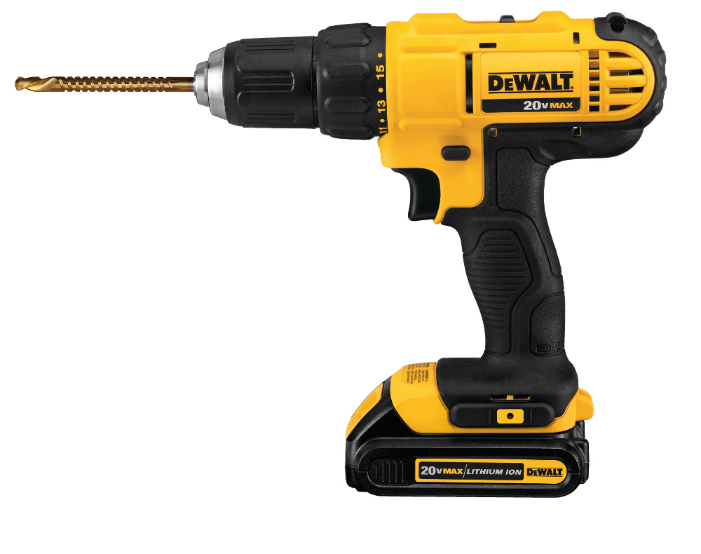
| Driver / Power Drill |
DeWalt DCD771 | Morris 13042 5/16″ saw drill bit |
Variable 2-speed, max 1500 RPM |
Squeeze trigger fully | ● Used at DARPA Testbed in 2015. |
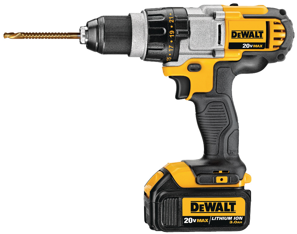
| Driver / Power Drill |
DeWalt DCD995 M2 | Morris 13042 5/16″ saw drill bit |
Variable 3-speed, max 2000 RPM |
Squeeze trigger fully | ● Used at DRC Finals in 2015. ● Motor runs for 5 minutes after squeezing trigger. |
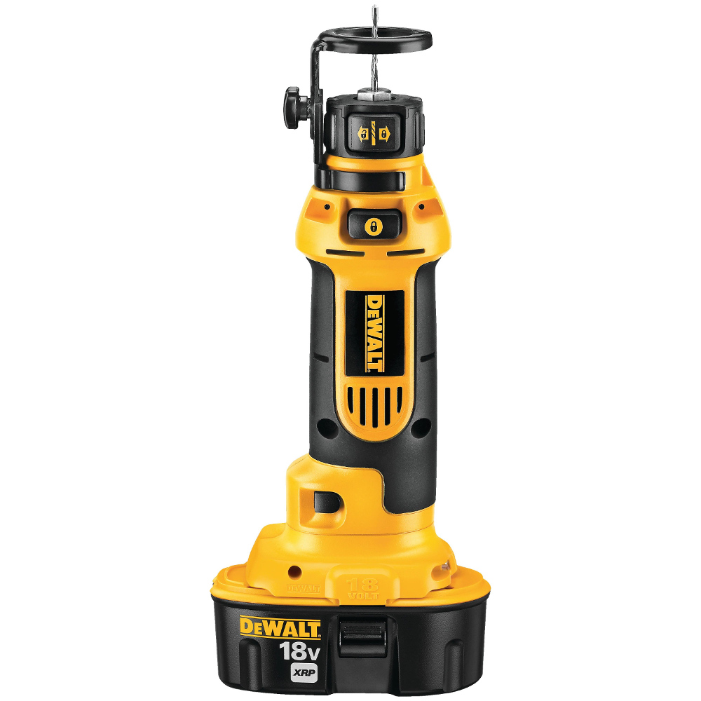
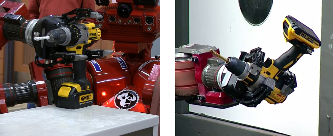
The cut-out tool is specifically designed for cutting drywall panels, so it seems like the obvious choice. It has a higher RPM than the power drill and can cut holes in thick drywall using less force at the cutting tip. However, the on/off button is smaller and stiffer than a trigger mechadnism. This makes it more difficult to activate, normally requiring two-handed manipulation. And the cutting bit is very small diameter, meaning it’s prone to fracturing (snapping) if not inserted precisely perpendicular to the drywall panel.
The cordless drill can be operated with only one hand, assuming one has sufficient dexterity to hold the handle and independently squeeze the trigger. The drill has a white LED that illuminates when the trigger is partially or completely pressed. This means the robot would not have to listen for sound or see that the drill chuck is rotating. However the drill has a timer and the motor only runs for 5 minutes before the trigger must be released and pressed again.
The newer model DeWalt DCD995 cordless drill is slightly more bulky than the DCD995. Also the width from the front of the trigger to the back of the handle is 7mm larger. This means that the DCD995 is more difficult to manipulate using the Robotiq gripper.
| Sensor | Method | |
| 1 | Microphone in palm or wrist | Detect sound of motor |
| 2 | Camera | Use a high-resolution camera to check if cutting bit is rotating. |
| 3 | Camera | Some power tools have an LED that illuminates when trigger is pressed. |
| 4 | Force/Torque sensor in wrist | Push tool bit against wall, check if penetrates the wall. |
To verify that a power tool is operating correctly, humans use their ears to check for a familiar sound based on their prior experience. We can tell if the tool chuck is spinning and the battery has sufficient power. We also do a quick visual check to see that the cutting bit is not broken or clogged.
CHIMP wasn’t designed with any “ears” (microphone), which precluded that option. Placing a microphone on the robot’s limbs would require an analogue-to-digital convertor to send a signal back along the data bus, similar to the force-torque sensors located on the wrists.
To capture the spinning motion of a tool chuck requires a high-resolution camera. At low resolutions, a spinning chuck is indistinguisable from a stationary chuck. CHIMP’s vision system was designed to perform heavy hardware-based compression of the camera images so they could be transmitted over a wireless link. There was no capability to request a “one shot” high-resolution image, which precluded that option.
The robot does have the capability to measure forces exerted on the wrist, to check if the tool is working. However, restarting the entire process to re-squeeze the trigger and re-check the tool operation would be very time consuming.
Grasps:
For each type of tool, various grasping strategies were considered (Table 3). Each “grasp” is a method for a specific gripper to pick-up that tool. Some grasps only allow simple pick-and-place behaviour. However, if a gripper has sufficient dexterity then more complex manipulation tasks can be achieved. Alternatively it may be possible to use a re-grasping policy to achieve complex manipulation, but that is not covered here.
| Tool type | No. of hands | Grasp type | Description | Example(s) | |
| 1 | Rotary Hammer / Power Drill |
2 | Power – palm, Power – wrap |
Two hands: Support tool with one hand, squeeze trigger using forefinger of second hand. (like a human) |
 |
| 2 | Cut-out tool | 2 | Power – wrap, Precision – poke |
Two hands: Grasp tool with one hand, press on/off button using finger of second hand. (like a human) |
 |
| 3 | Cut-out tool | 2 | Power – wrap | Two hands: Grasp tool with one hand, poke the on/off button using a stick attached to the second hand. |
 |
| 4 | Cut-out tool | 1 | Power – wrap | Grasp handle, poke the on/off button by pushing it against a protrusion located on robot’s torso. |
|
| 5 | Cut-out tool | 1 | Power – wrap | Grasp handle using enclosing-power grasp, pressing the on/off button at the same time using a protrusion in palm of gripper. |
 |
| 6 | Power Drill | 1 | Power – medium wrap + finger hook |
Grasp handle, independently squeeze the trigger with one finger. (like a human) |
 |
| 7 | Power Drill | 1 | Power – wrap / Cylindrical | Grasp handle using power grasp, squeezing trigger at same time. (there is not sufficient dexterity to independently press the trigger) |
 |
| 8 | Power Drill | 1 | Tripod + finger abduction |
Grasp the drill body, squeeze trigger by abduction of 2 fingers in “scissor” motion. |
 |
The Robotiq gripper was capable of grasping the power drill using grasp types #7 or #8. With grasping strategy #7 the fingers are closed around the handle using a “power-cylindrical” grasp whilst simultaneously pressing the trigger. Unfortunately the drill shifts in the gripper while the fingers are closing, so it’s difficult to determine the location of the cutting bit without re-localizing the drill pose. Also when the tool stops working after 5 minutes, it’s not possible to re-press the trigger without placing the drill back on a flat surface.
We wanted the ability to independently trigger the drill because it took a long time to compute the motion plan and cut the wall. Therefore we used grasp type #8, whereby the drill is cradled using two spread fingers (see Fig. 7 below), similar to how a human might hold a wine glass. The trigger is pressed by spreading the two fingers sideways in a “scissor” motion (abduction and adduction). This “scissor” action works best if the drill is held upside-down using the 3rd (middle) finger.
In conclusion, it was decided to use the power drill with grasp type #8, and check the tool’s operation by looking for the LED light.
The power drill was selected for the following reasons:
- It has an LED light that indicates when the tool is operating.
- The robot could grasp the drill and actuate the trigger using only one hand. This meant the robot could still accomplish the task if one arm or gripper was broken.
- The cutting bit in the power drill is larger diameter, meaning the strong robot was less likely to snap it.
Positioning the Robot Base:
We developed a planning module that computes the optimal 2D pose of the robot’s base relative to an object. For each task, like grasping the drill, the object’s graspability [7] is pre-computed offline and stored in a discrete cost-map. The navigation system them moves the robot to the position with maximum graspability.
However, we found that an experienced operator could tele-operate the robot’s base faster than the autonomous planning and navigation system. The operator is guided by task-specific, graphical guide markers that are overlaid on the robot’s view of the environment.
Object Recognition:
Object Pose Detection:
- Crop point cloud in a sphere around the selected point.
- Down-sample point cloud to match resolution of the object model point cloud.
- Detect dominant horizontal plane (the shelf) using RANSAC, remove those points.
- Try to detect vertical plane using RANSAC, remove those points.
- Flatten remaining points onto horizontal plane.
- Compute dominant axis using PCA (Principal Component Analysis).
- Align object model lengthways to the dominant axis.
- Generate 6 candidate poses around vertical axis: -30°, 0, +30°, -150°, -180°, +150°.
- For each pose, run ICP for N iterations.
- Keep best object post (max inliers, min error).
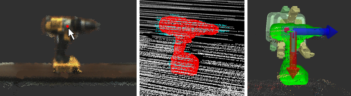
4.a: (left) The operator identifies the tool in the scene and selects it using the mouse.
4.b: The LiDAR pointcloud is cropped (cyan colored points) and the 3D model is fitted (red).
4.c: The grasp pose is where the gripper should be with respect to the drill.
The robot must be positioned such that the LiDAR sensor scans both the length and one end of the power drill, so that the cutting bit is visible in the shape silhouette. One issue was that the orientation and spin-rate of the LiDAR sensor was optimized for SLAM and collision-avoidance. The fast rotation rate of the LiDAR is important to avoid hitting objects when the robot is moving quickly, however it is less accurate for object pose detection. When capturing a point cloud of an object like a tool or door handle, the “lapping” pattern of the LiDAR creates increased distance error and a lower-density pointcloud. In contrast to this, other teams in the DARPA Robotics Challenge used a LiDAR with a “spinning” pattern or a slow “knodding” scan.
We also experimented with storing object pose information in the world frame of the robot’s global pose frame, to build a map of known objects in the environment. However, the robot could not return and re-grasp an object due to error build-up from the localization system.
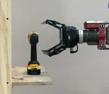
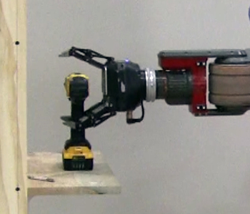
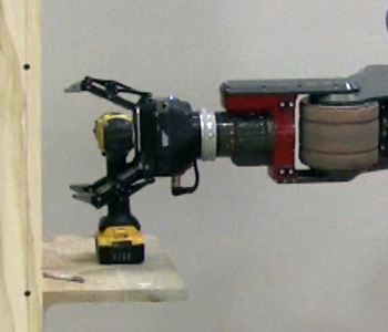
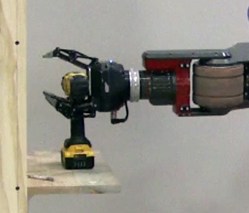
Grasping the Tool:
The power drill is grasped using grasp type #8 (see Table 3 above), as shown in Figs. 5-6.
The grasping policy is a multi-step process, fusing gripper state and force measurements from the wrist to autonomously grasp the drill. The approach was inspired by [9], using the detected forces to “feel” the location of the drill in the presence of object pose uncertainty and arm compliance.
In the initial phase, a “caging” grasp [10] uses gravity to cradle the drill in 2 fingers (see Fig. 6d below), similar to how you might hold a wine glass. The final phase uses a force-closure grasp (see Fig. 6g below), where the drill can’t slip within the gripper fingers.
The grasp policy is implemented in code using a state machine:
- Move gripper to pre-grasp pose.
- Open all fingers.
- Move gripper forward in straight line so that palm is 30mm away from drill.
- Move gripper forward again until palm touches drill, ★
with fingers around the drill body. - Half-close bottom 2 fingers to cradle the drill body.
- Move gripper sideways so finger touches back of drill handle, ★
ensuring other finger is in front of the trigger. - Move gripper down so top (middle) finger presses on top of drill. ★
- Close top (middle) finger.
- Close bottom 2 fingers.
- Move gripper up and back, to lift the drill above shelf.
★ = Action uses force sensor in wrist.
 6.a: Pre-grasp pose. |
 |
 |
 |
 |
 |
 |
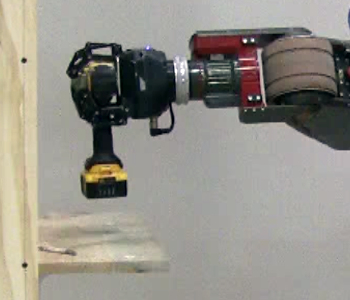 |
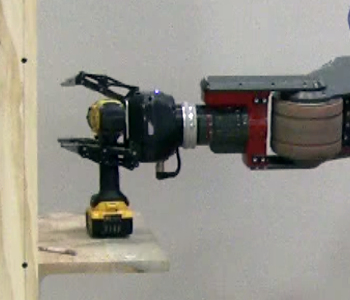
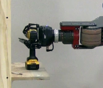
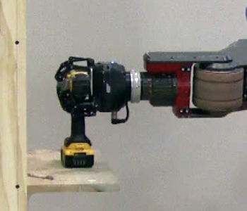
Actuating the Drill Trigger:
The robot squeezes the drill trigger twice; once to check that it can activate the drill, and the second time when ready to cut the wall. The power drill only operates for 5 minutes, after which the trigger has to be pressed again. If grasped poorly, the gripper fingers may have gotten stuck on the trigger, or stuck in a position that they could not press the trigger. In this situation the operator can command the robot to re-grasp the same tool, or try to grasp a different one.
The robot rotates the drill upside-down and releases 2 of the 3 fingers. In this caging grasp [10], the body of the drill is held using the middle finger and the force of gravity, while the other 2 fingers “cage” the side of the handle. These 2 fingers both support the grasp and make the “scissor” motion required to squeeze the trigger.
The sequence of actions to actuate the drill trigger is implemented using a state machine:
- Move drill so the robot’s camera can see the LED light on the drill.
- Take a photo of the light (which should be turned off).
- Rotate the wrist joint so the drill is horizontal, upside-down & supported by one finger.
- Squeeze the drill trigger.
- Release the trigger.
- Rotate the wrist back so the robot is looking at the LED light again.
- Take second photo of the light (it should be lit).
- Wait for human operator to verify.
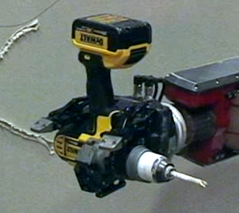 8.a: The drill is held upside-down with the middle finger tightly closed. |
 8.b: The outer fingers are squeezed inwards together (abduction). |
 8.c: All fingers tightly closed around drill body. |
|
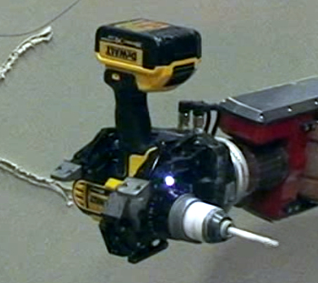
After pressing the trigger a white LED light indicates that the tool is operating. The system presents an image to the operator showing the light “before” and “after” squeezing the trigger. It is possible to check the light status automatically using computer vision, however the light is barely perceptible to the human eye when operating the robot outdoors in the sun. An alternative approach was to capture a photo of the tool chuck rotating, however the operator can only see a low-resolution image.
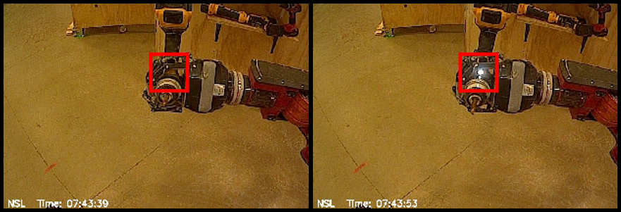 9.a: (left) Light is off. 9.b: The light is on, after squeezing trigger. |
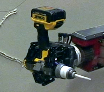
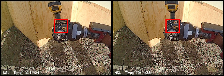 10.a: (left) Light is off. 10.b: Light is on. It looks similar to the metal pin joints of the finger. |
Wall Pose Detection:
Arm Motion Planning:
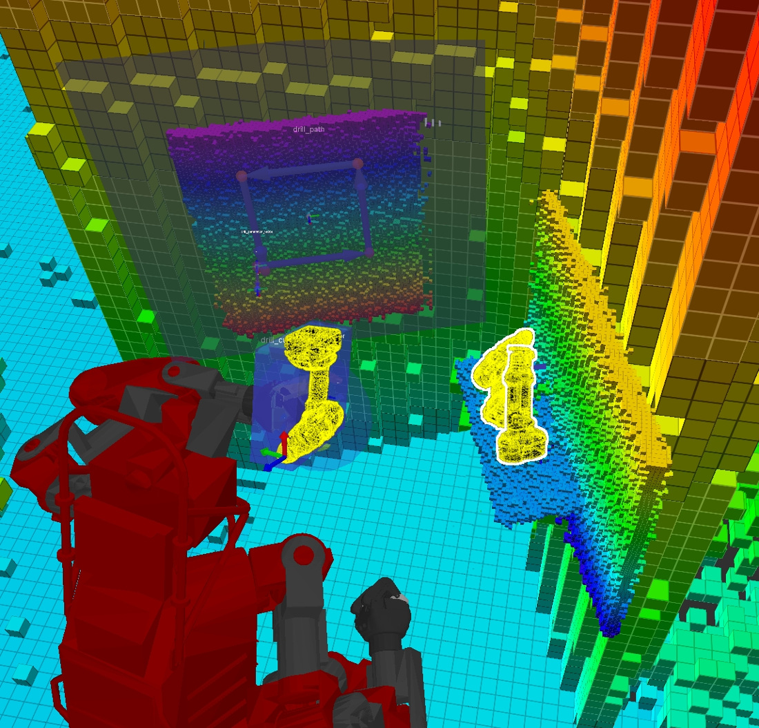
The environment around the robot is modelled using a Voxel Grid generated from the spinning LiDARs. The grid has a coarse resolution with a high update-rate and is used by the motion planner to ensure the arm does not collide with any obstacles. When the perception system detects a known object, the ROI (Region of Interest) is replaced by a high-resolution voxel grid and the object is replaced by a cuboid shaped bounding box. The robot’s geometry is modelled using either spheres or cuboids.
For generating the arm motions we used a probabilistic motion planning approach based on RRTs (Rapidly Expanding Random Trees) [11, 12]. This generates a trajectory of joint-space configurations where each waypoint W_j = {t (sec), joint_angle_i (rad)}. Two variants of the RRT algorithm are used, each with different capabilities and performance (Table 4).
| Gripper motion | Motion constraints | Algorithm | Geometry for collision-checking | Performance |
| Free-space | ● Joint angles ● Pose of gripper (wrist link) |
RRT-Connect [11] | Spheres | Fast |
| Cartesian motion (along a line) |
● 3D vector ● Position tolerance (m) |
RRT-Connect [11] | Spheres | Fast |
| Path-following | ● 3D position ● Angle tolerance (rad) ● Position tolerance (m) |
CBiRRT2 [12] | Cuboids | Slow |
During motion planning, the planner checks for collisions between the robot, the world and any known objects. To manipulate or grasp an object, collision-checking between the gripper and object is briefly disabled. This allows the planner to put the gripper fingers around the drill handle or to move the tool through the wall. When the robot grasps an object like the drill, the object’s bounding box is deleted from the world model and attached to the robot’s geometry tree. The motion planner is aware that the tool can penetrate the cutting zone but must not collide with the surrounding wall, the shelf or the ground.
The planner outputs a feasible joint-space trajectory, however the number of waypoints and the cartesian velocity can vary greatly due to the nature of probabilistic planning. Another issue is that the arm can make big motions that have little effect on the tool point position, such as when the arm needs to pass-through the null-space or “flip” between redundant arm configurations. These issues could be solved by using a constraint-aware post-processing algorithm or an optimization-based motion planner. Currently we use a trajectory re-timing algorithm, whereby we keep the same number of waypoints but scale the velocity and acceleration to maximize trajectory-wide constraints. The overall planning process (constrained RRT + retimer) is executed multiple times in parallel and the best trajectory is kept, based upon minimum number of waypoints and maximum total path velocity.
Discarding the Tool:
Results & Discussion:
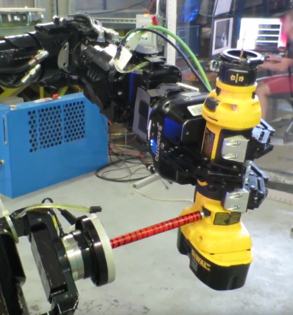
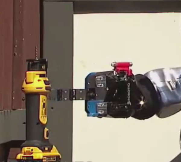
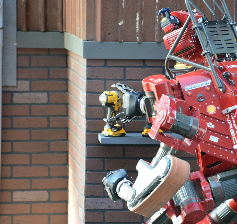
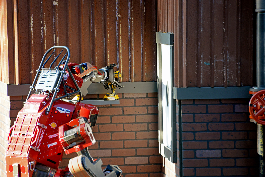
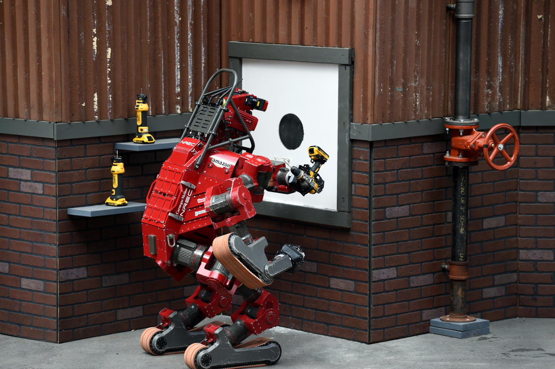
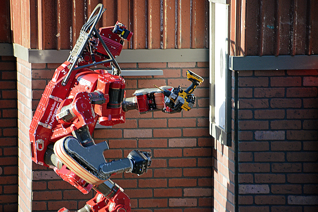
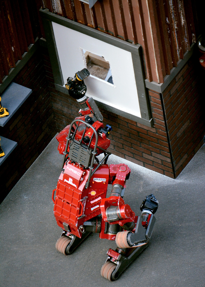
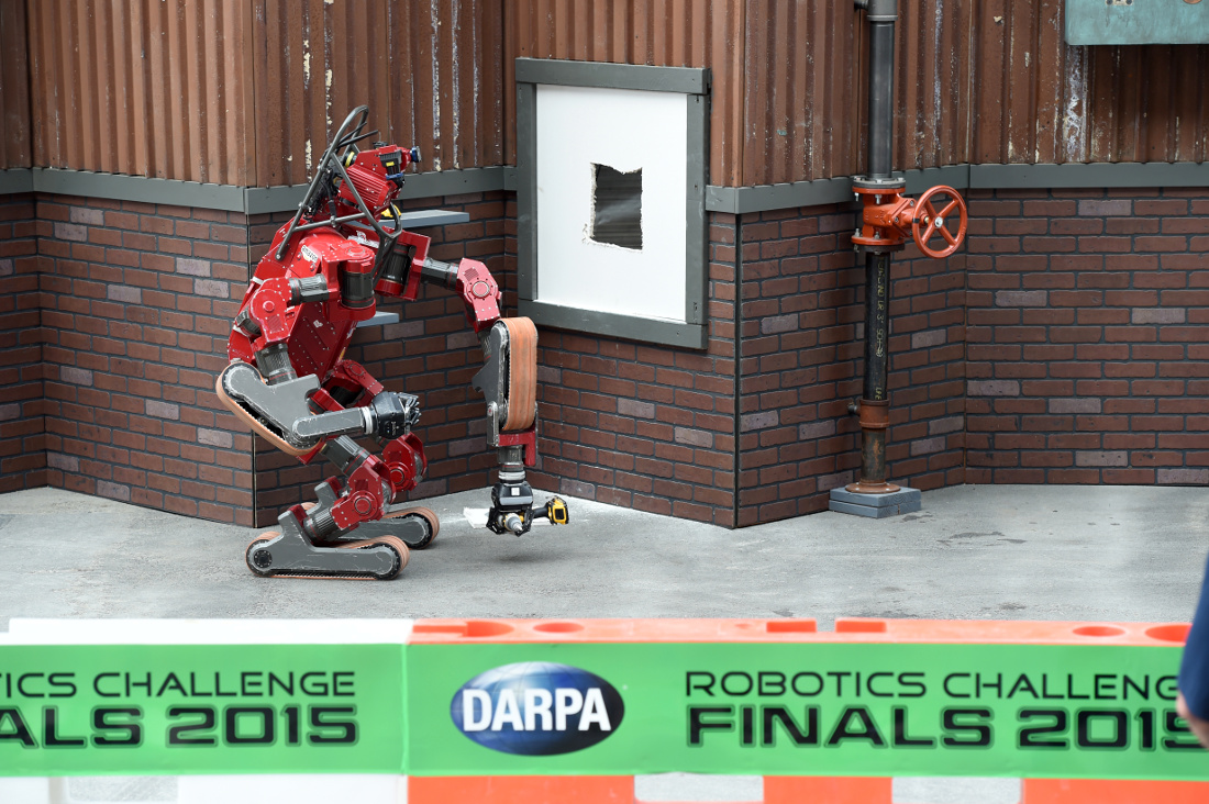
The photos below (Figs. 12-19) show CHIMP cutting a hole in a wall at the DARPA Robotics Challenge, in an outdoor mock-up environment.
 |
 |
 |
 |
 |
 |
 |
 |
For the DARPA Robotics Challenge we chose to cut a square hole because our software implementation of CBiRRT2 [12] had some problems with circular holes, due to how rotation constraints are represented. Currently the planner is constraining the rotation of each arm joint and the tool tip to be +/- 180°. However, the robot’s arm joints are capable of continuous rotation and obviously a rotary tool should be free to rotate around the axis of the cutting bit. We found during experiments that the robot could perform square cuts (straight lines) at higher speed and with lower joint torques.
The one-handed, ambidextrous approach for manipulation proved to be useful in the DRC Finals. On day 1 of the competition the robot fell on its right arm. This caused clutch slippage in the arm joints which meant the arm lost calibration of the “home” configuration. After initially trying the right arm, the operator identified the problem and commanded the robot to use its left arm to successfully perform the task.
Unfortunately we had some other problems at the competition. We had developed and tuned a grasping strategy to manipulate a specific model of power drill. The competition organiser decided to use a different power drill which had different physical dimensions. The DeWalt company seems to release a new model of power drill every year, with an updated design that is different to the old model. The shape of the handle was thicker, and the width from the front of the trigger to the back of the handle was longer, meaning the gripper could not physically wrap around it as well as before. In contrast, the design of the cut-out tool did not change much during the same time period.
One day 1 of the competition, while halfway through cutting the wall, the drill’s spinning chuck started pushing too hard against the wall and started to overload one of the arm joint motors. If a motor overloaded it would cause the joint to “relax”, making it more difficult to resume the task. Therefore the operator intervened and commanded the robot to stop moving the arm, then adjusted the cutting depth, and then resumed the cutting action.
On day 2, our attempt at the overall challenge was less successful. There was a communications problem between the robot and the operators’ control room. There were multiple human operators who had trained for specific tasks, each with a laptop computer. On this day, additional laptops had been connected to the TCP/IP network to watch the action, more than had ever been connected before. The “master” computer needs to send N number of messages to each computer. The finally-tuned network was pushed over its limit, causing status and control messages to arrive “late” or disappear. The robot grasped the drill and then asked the operator for instruction, but then erroneously put the drill down on the ground.
In the DRC Finals, our team (Tartan Rescue) was one of only 2 teams to use the power drill for the wall cutting task. Most teams opted to use the specialised cut-out tool for cutting the hole. The winning team KAIST used a two-handed approach to grasp and activate the cut-out tool. Instead of detecting the exact location of the on switch, the robot tried to press its finger in multiple places until the motor’s noise was detected by a microphone. This two-handed strategy does have a risk, for example the MIT team was unable to use the tool after the robot fell over and broke one arm. In contrast, the second-place IHMC team used a novel one-handed approach, grasping the cut-out tool using a Robotiq gripper that automatically pressed the on switch using a piece of plastic attached to the palm.
Future work will be to:
- Add position encoders to the output shaft of each joint.
- Improve the motion planner to maximize the force at the cutting tip, whilst ensuring the arm joint torques are balanced throughout the arm.
- Develop a method to more accurately set the depth of the cutting bit.
- Implement a hybrid position-force controller to execute the cutting trajectory.
- Experiment with using the cut-out tool.
This work was conducted with J. Gonzalez-Mora, D. Anderson, K. Strabala and C. Dellin at CMU (Carnegie Mellon University)
and NREC (National Robotics Engineering Center).
| References: |
|
[1] G. C. Haynes, D. Stager, A. Stentz, B. Zajac, D. Anderson, D. Bennington, J. Brindza, D. Butterworth, C. Dellin, M. George, J. Gonzalez-Mora, M. Jones, P. Kini, M. Laverne, N. Letwin, E. Perko, C. Pinkston, D. Rice, J. Scheifflee, K. Strabala, J. M. Vande Weghe, M. Waldbaum, R. Warner, E. Meyhofer, A. Kelly and H. Herman, “Developing a Robust Disaster Response Robot: CHIMP and the Robotics Challenge”, Journal of Field Robotics, Vol. 34, No. 2, March 2017.
|
|
[2] L. Bridgwater, C. Ihrke, M. Diftler, M. Abdallah, N. Radford, J. Rogers, S. Yayathi, R. Askew and D. Linn, “The Robonaut 2 hand – Designed To Do Work With Tools”, IEEE International Conference on Robotics and Automation (ICRA), May 2012.
|
|
[3] D. Hackett, J. Pippine, A. Watson, C. Sullivan and Gill Pratt, “An Overview of the DARPA Autonomous Robotic Manipulation (ARM) Program”, Journal of the Robotics Society of Japan, Vol. 31, Issue 4, January 2013.
|
|
[4] G. Cheng and A. Zelinsky, “Supervised Autonomy: A Framework for Human Robot Systems Development”, IEEE International Conference on Systems, Man, and Cybernetics (SMC), October 1999.
|
|
[5] B. Pitzer, M. Styer, C. Bersch, C. DuHadway and J. Becker, “Towards Perceptual Shared Autonomy for Robotic Mobile Manipulation”, IEEE International Conference on Robotics and Automation (ICRA), May 2011.
|
|
[6] B. Sankaran, B. Pitzer and S. Osentoski, “Failure Recovery with Shared Autonomy”, IEEE/RSJ International Conference on Intelligent Robots and Systems (IROS), October 2012.
|
|
[7] S. W. Ruehl, A. Hermann, Z. Xue, T. Kerscher and R. Dillmann, “Graspability: A description of work surfaces for planning of robot manipulation sequences”, IEEE International Conference on Robotics and Automation (ICRA), June 2011.
|
|
[8] P. J. Besl and N. D. McKay, “A method for registration of 3-D shapes”, IEEE Transactions on Pattern Analysis and Machine Intelligence, Vol. 14, No. 2, February 1992.
|
|
[9] K. Hsiao, L. P. Kaelbling, T. Lozano-Perez, “Robust Grasping Under Object Pose Uncertainty”, Autonomous Robots, Vol. 31, Issue 2-3, October 2011.
|
|
[10] E. Rimon and A. Blake, “Caging Planar Bodies by One-Parameter Two-Fingered Gripping Systems”, International Journal of Robotics Research (IJRR), Vol. 18, No.3, March 1999.
|
|
[11] J. J. Kuffner and S. M. LaValle, “RRT-Connect: An Efficient Approach to Single-Query Path Planning”, Proceedings of the IEEE International Conference on Robotics and Automation (ICRA), April 2000.
|
|
[12] D. Berenson, J. Chestnutt, S. Srinivasa, J. Kuffner and S. Kagami, “Pose-Constrained Whole-Body Planning using Task Space Region Chains”, Proceedings of IEEE-RAS International Conference on Humanoid Robots (Humanoids), December 2009.
|