LiDAR was another popular technology at CES, due to its importance for self-driving vehicles.
In this section I’ve included photos and notes for various suppliers.
Also, Brad Templeton has a great technical round-up of LiDAR technology from CES 2018 on his blog:
ideas.4brad.com/tons-lidars-ces-2018
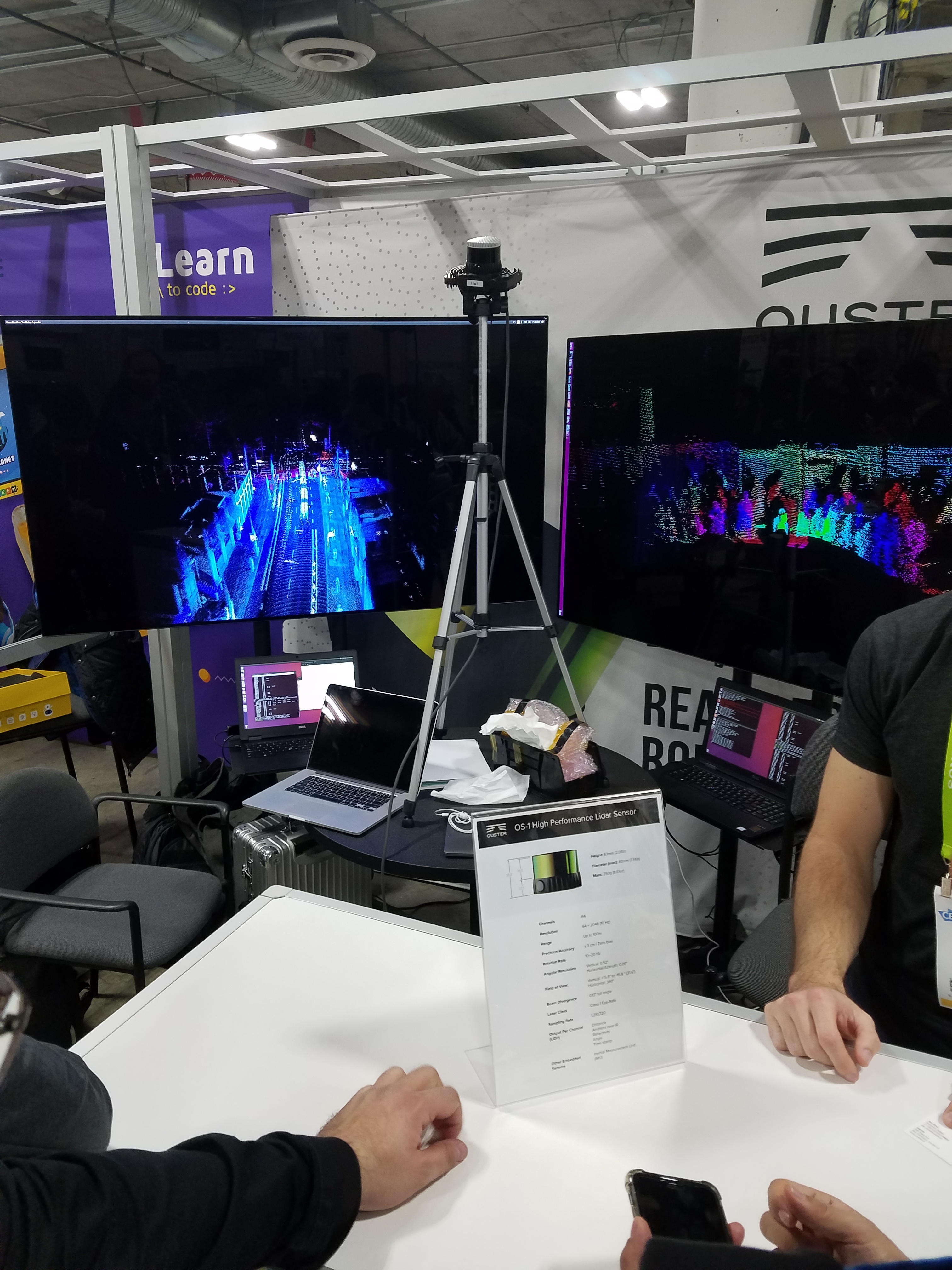
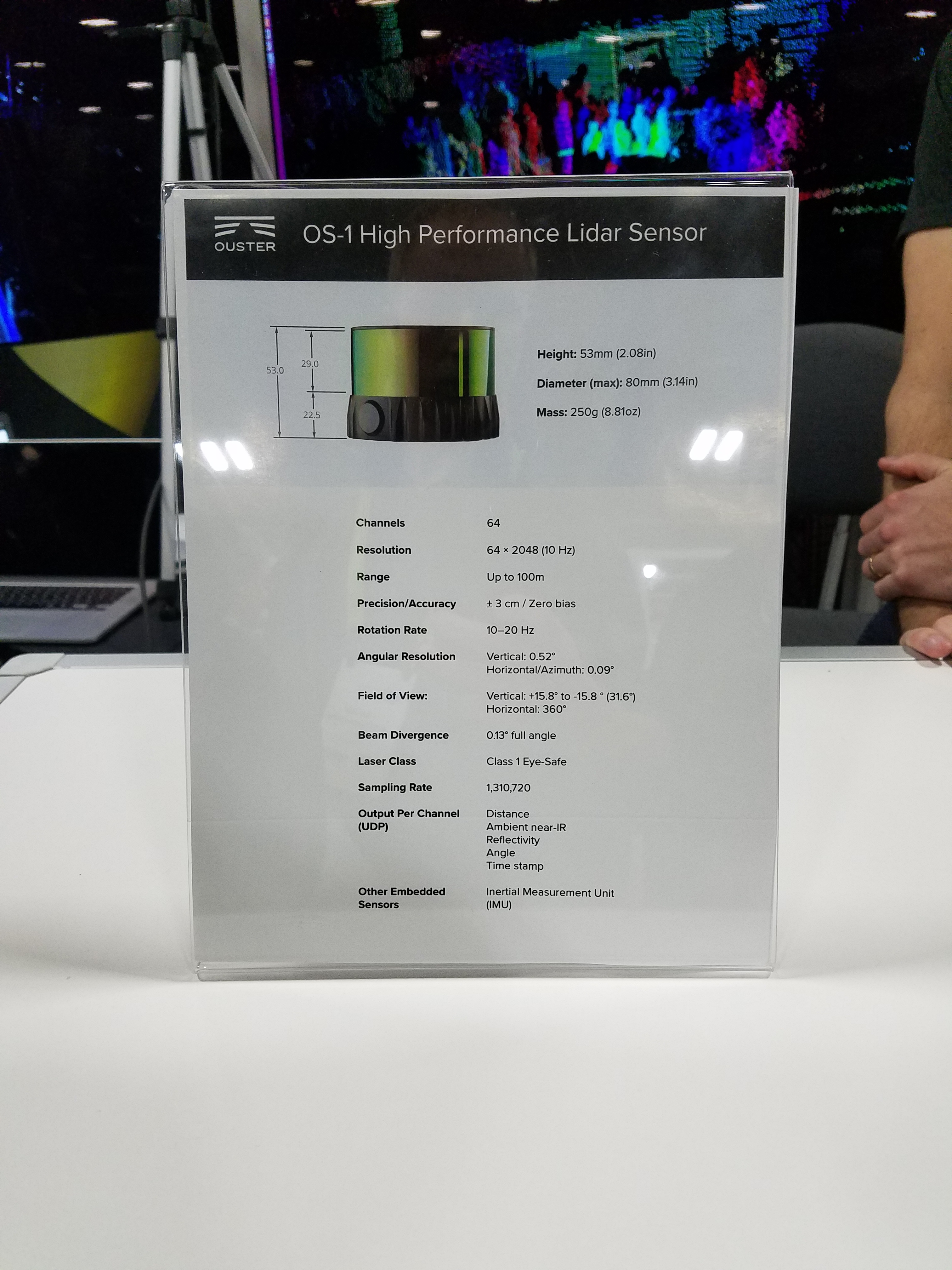
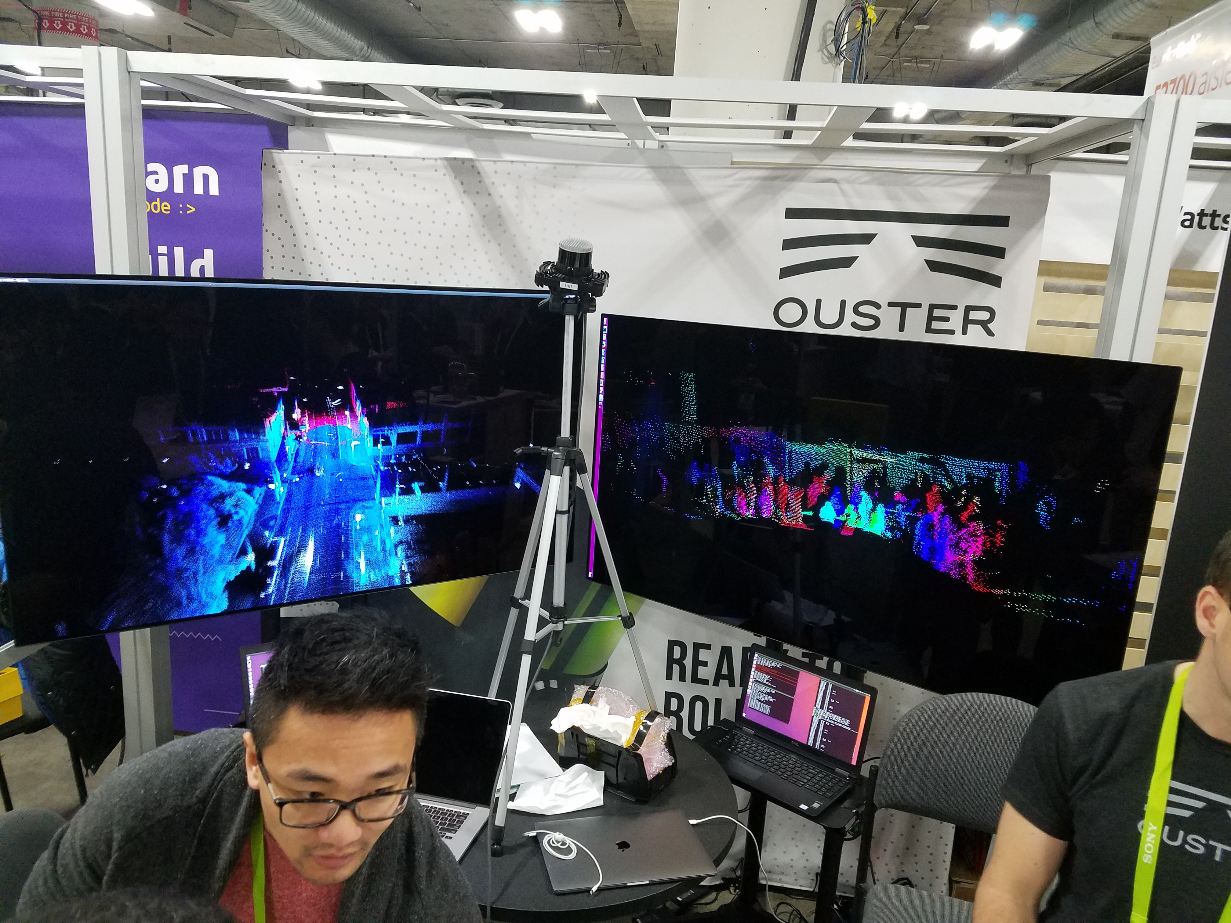
OS-1 by Ouster
There were lots of prototype LiDAR sensors at CES 2018, but the OS-1 was one of the few products that is ready to buy today.
It’s lighter than both the Velodyne VLP-16 “Puck” and “Puck Lite”, yet has 4 times the layer resolution (the number of laser beams you can see).
As of Jan 2018, the OS-1 has a price of $12000 or $8000 for educational institutions.
In the photo below, they show a point cloud that was fused together using GPS RTK (Fig. 1 and 2). The intensity data looks good and you can see the painted road markings stand-out from the asphalt surface. However, there is some visible “banding” in the intensity data which probably means the sensor is not well calibrated.
Website: www.ouster.io
|
Fig. 1: |
Fig. 2: |
Fig. 3: |
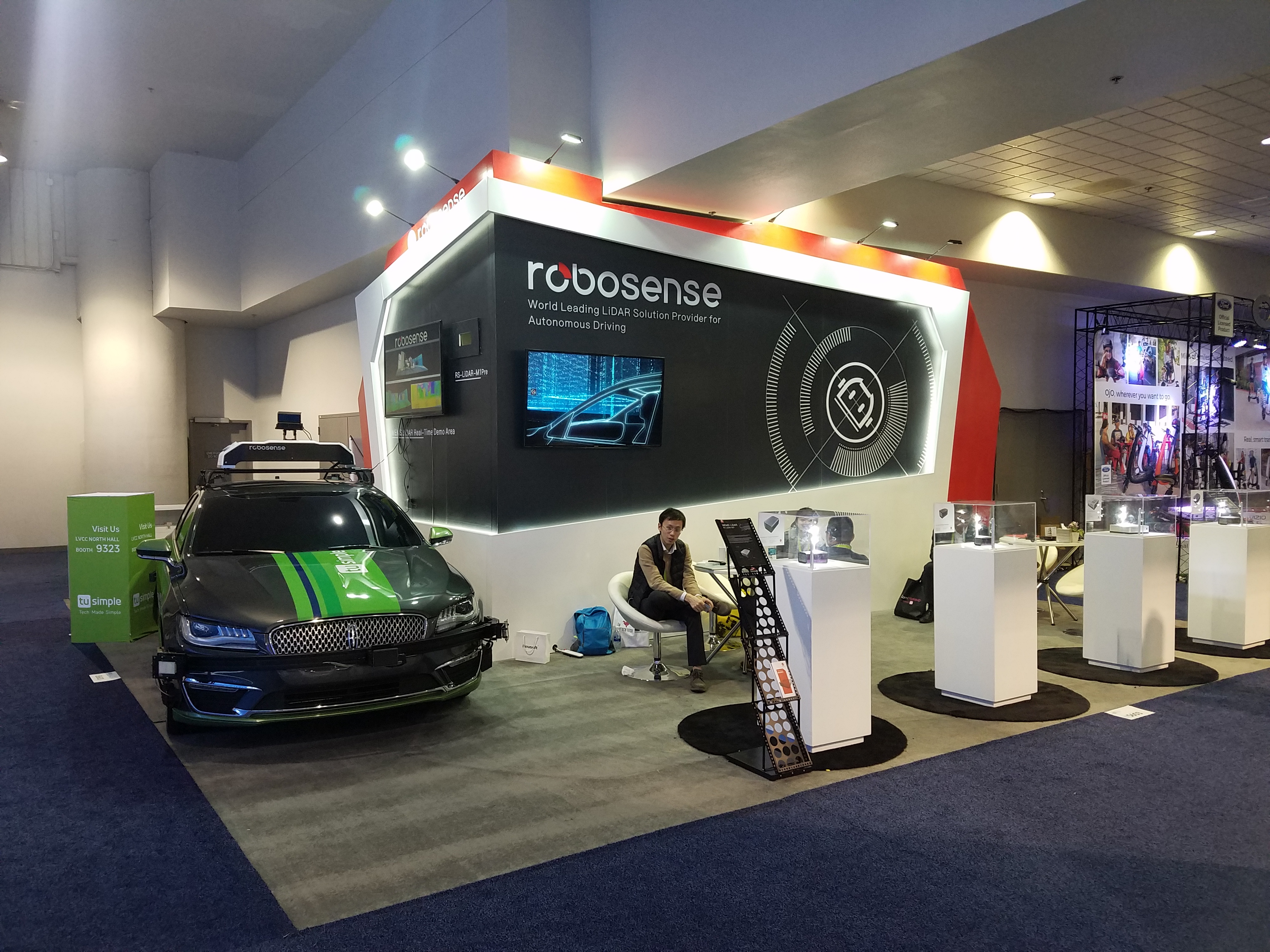
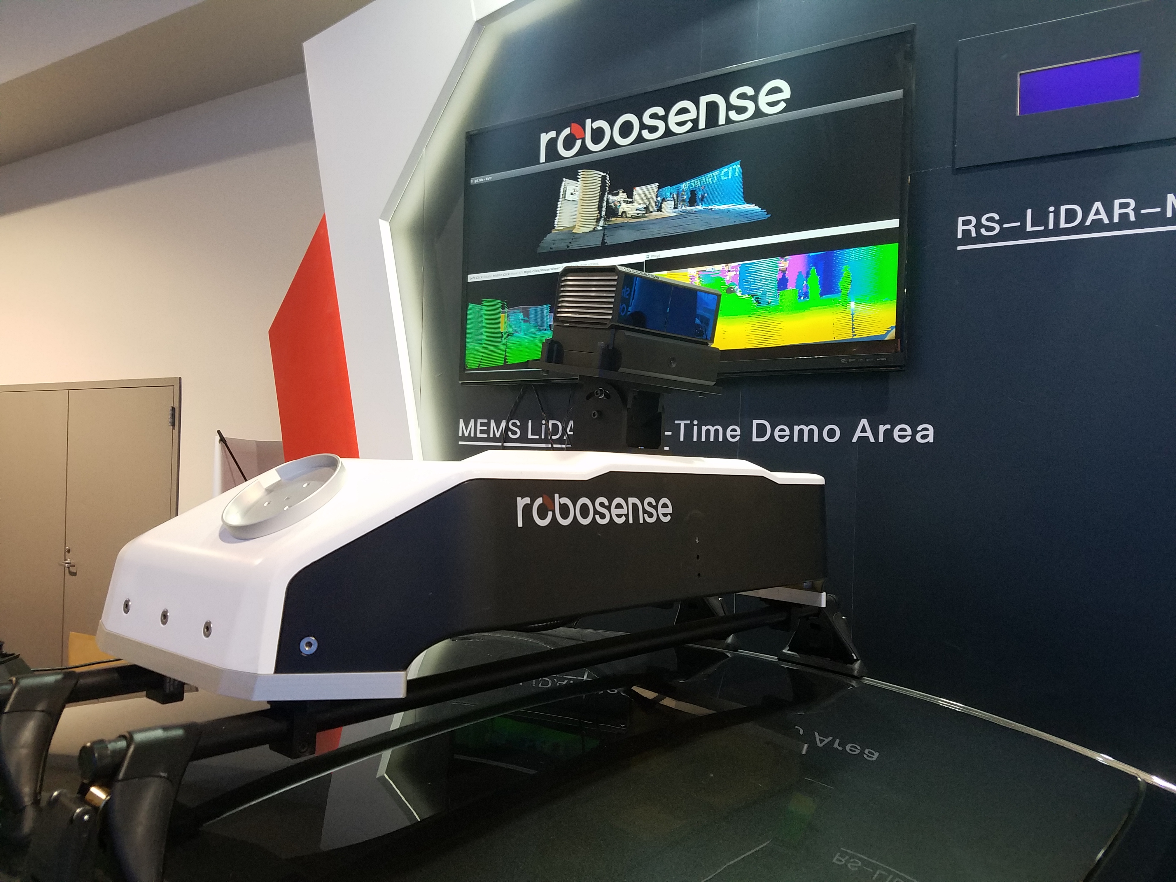
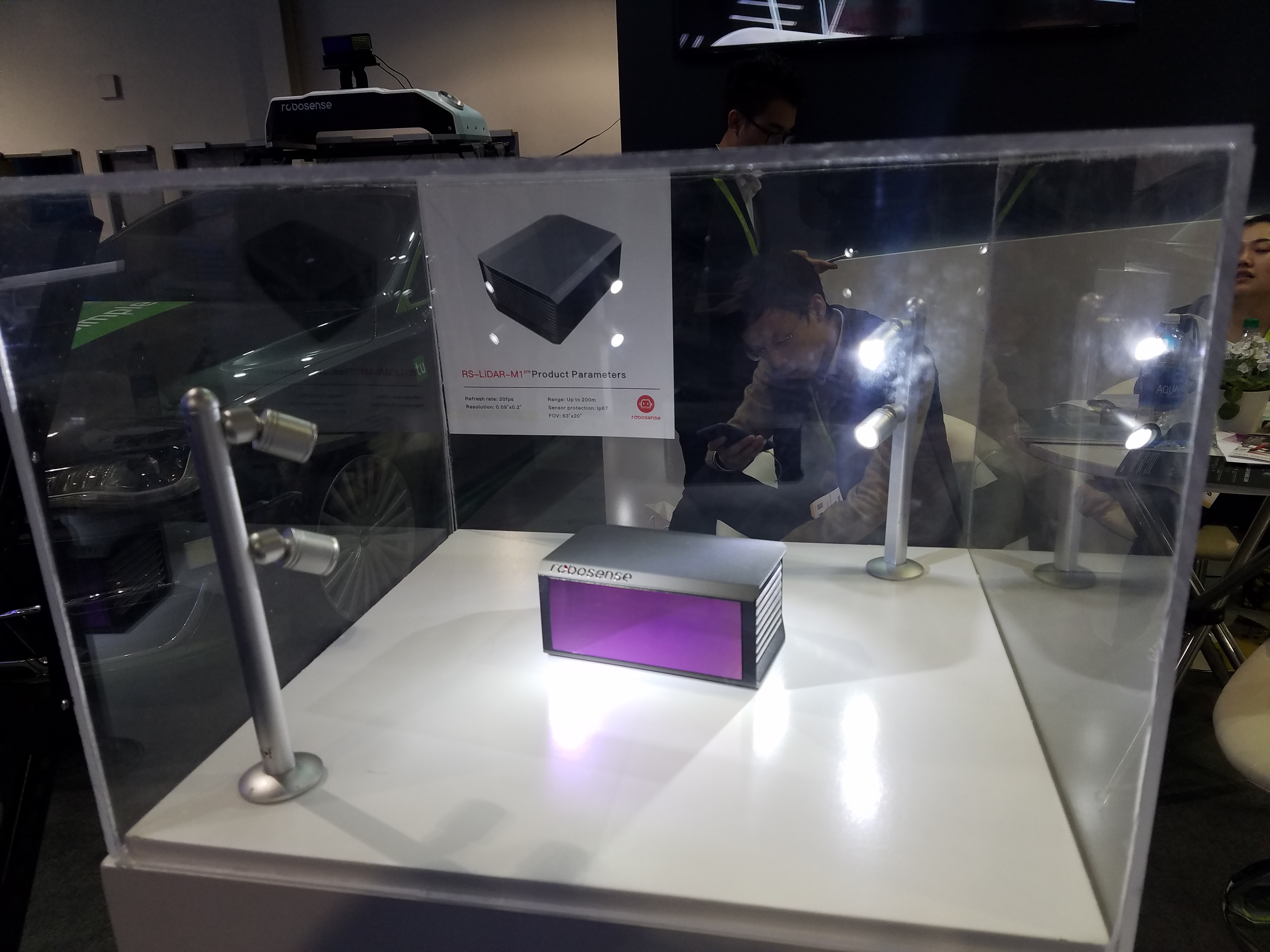
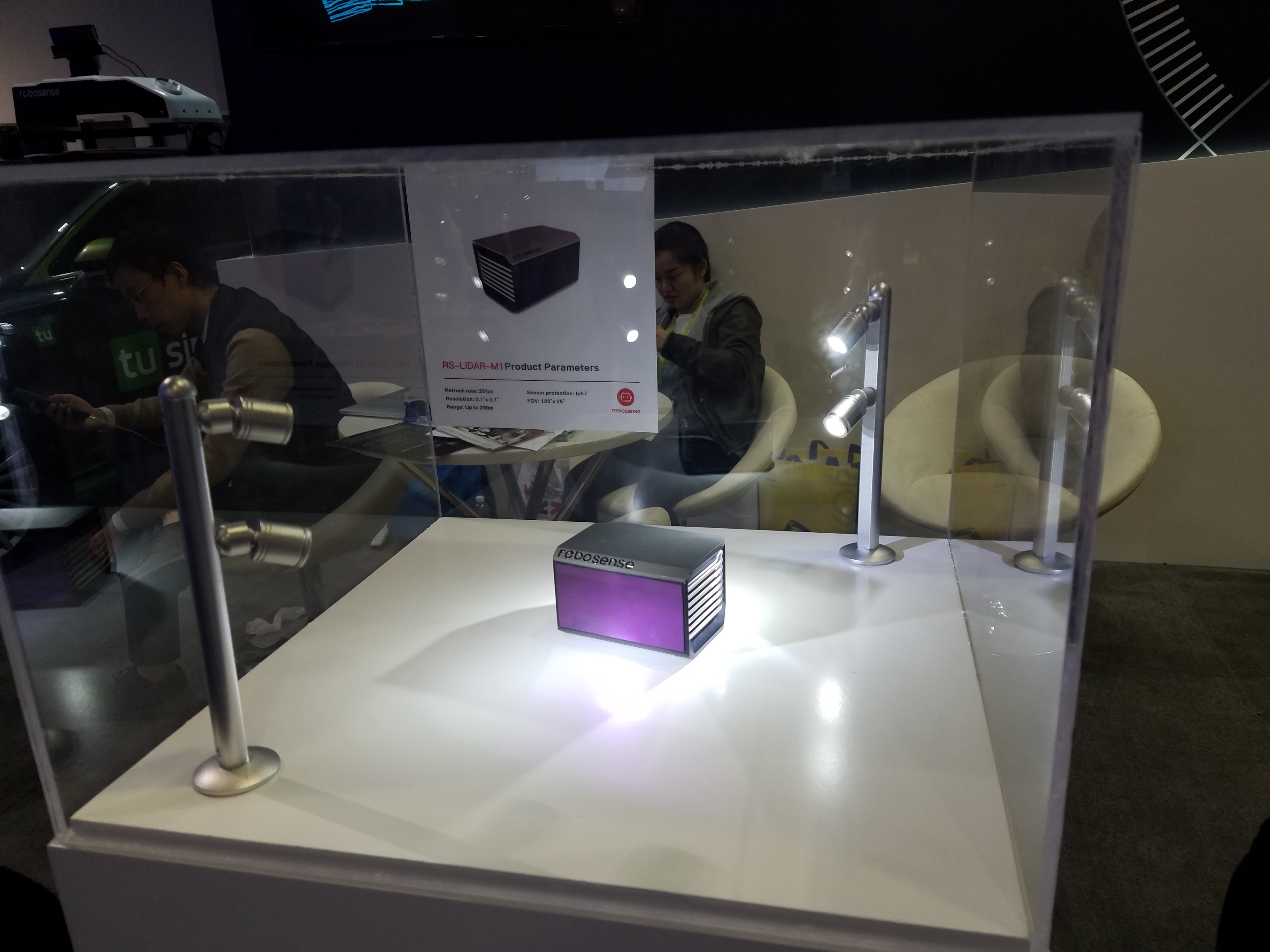
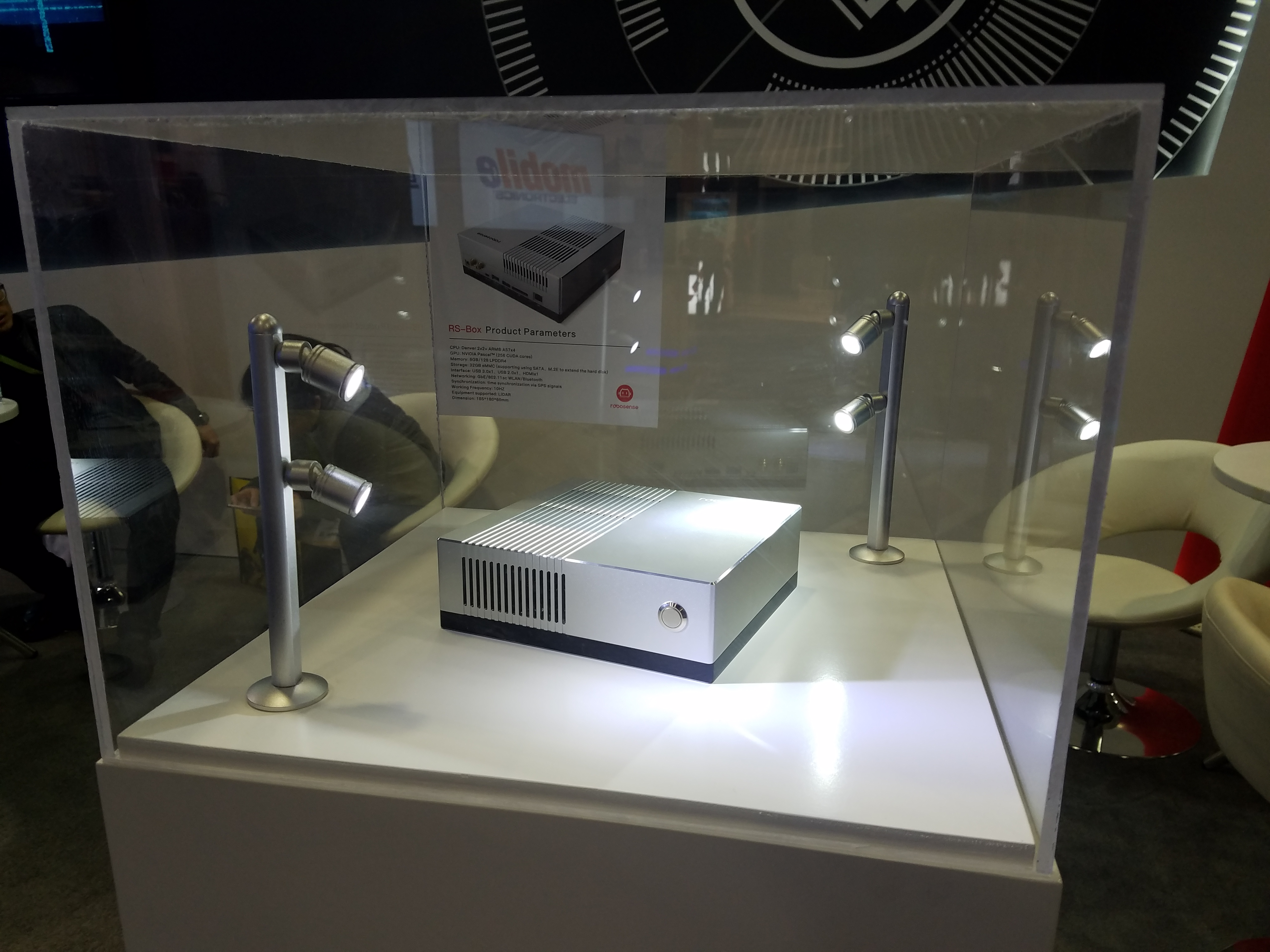
RoboSense (Suteng Innovation Technology Co. Ltd)
They were demonstrating their MEMs-based LiDAR called “RS-LiDAR-M1 pre” (Fig. 5).
Based on the patterns in the LiDAR data (see Video 2), it looks like they are using 3 MEMs scanning mirrors, compared to 4 in the InnovizOne, and 2 in the Luminar LiDAR.
This company has 16-channel (“RS-LiDAR-16”) and 32-channel LiDARs (“RS-LiDAR-32”).
Approximate prices are $5,000 and $27,000.
Here is an article comparing the RS-LiDAR-16 with the Velodyne VLP-16:
Wang et al., “Characterization of a RS-LiDAR for 3D Perception”, arXiv 2017 PDF
They also have a terrestrial LiDAR scanner called “Seeker”, which looks similar to the Faro.
Website: www.robosense.ai
|
Fig. 4: |
||
|
Fig. 5: |
Video 1:
CES demo, showing camera and LiDAR fusion, with object tracking.  RoboSense |
Video 2:
Output of various algorithms using the MEMs-based LiDAR. 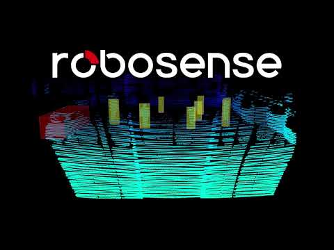 RoboSense |
|
Fig. 6: |
Fig. 7: |
Fig. 8: |
|
Video 3:
Demo of algorithms using data from from a roof-mounted RS-LiDAR-16. 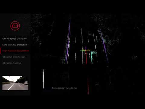 RoboSense |
Video 4:
Road view and localization using data from a RS-LiDAR-32. 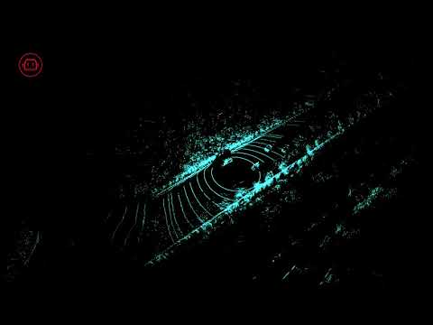 RoboSense |
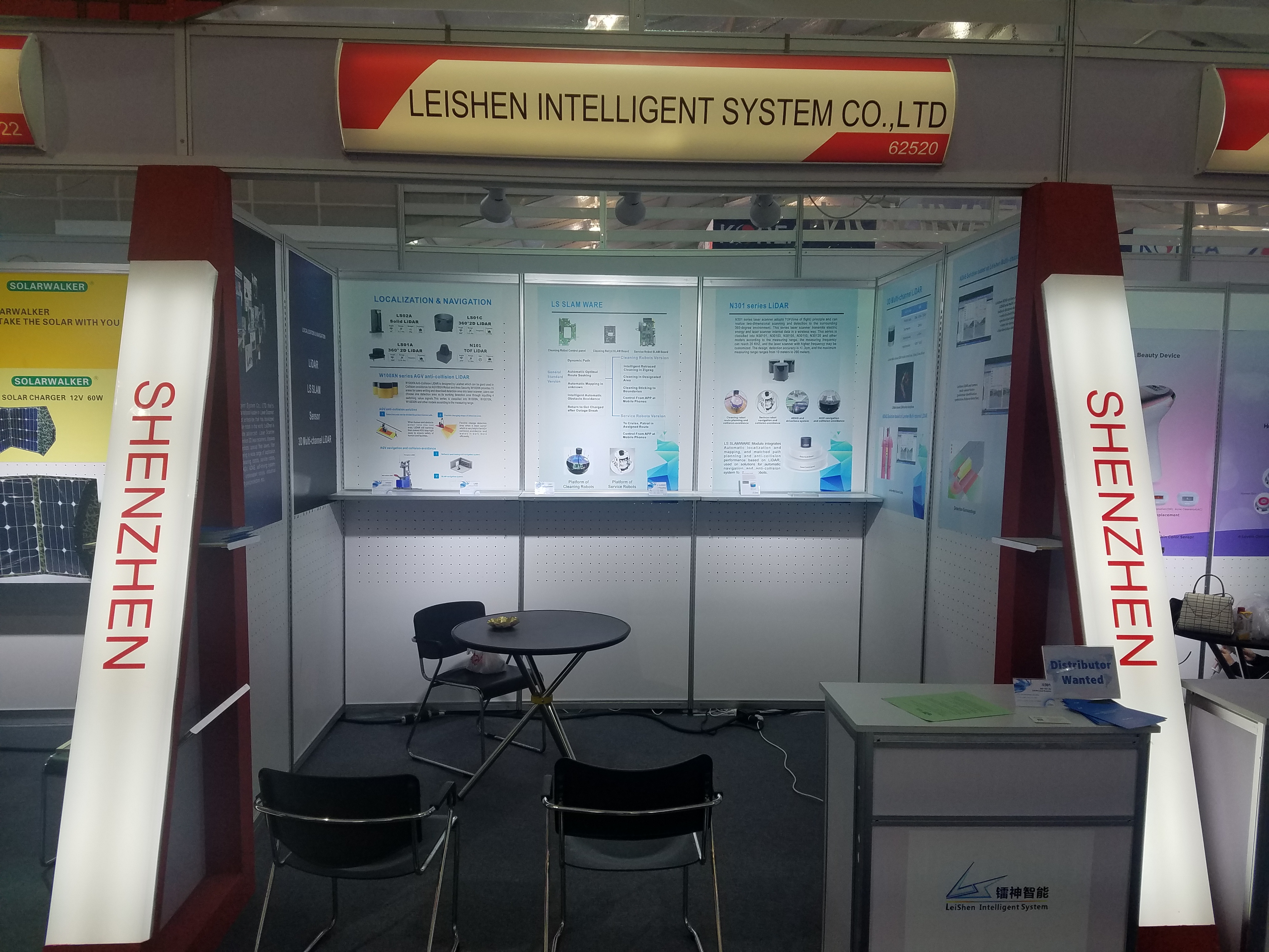
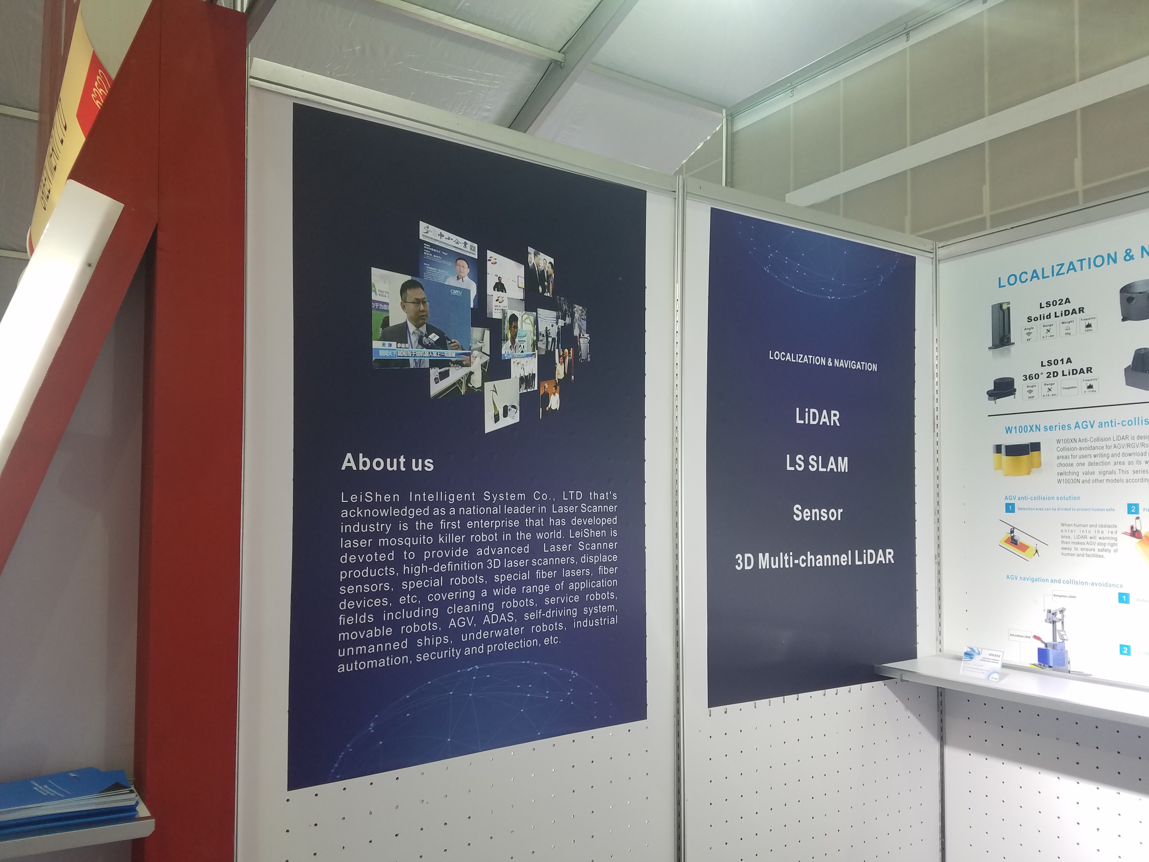
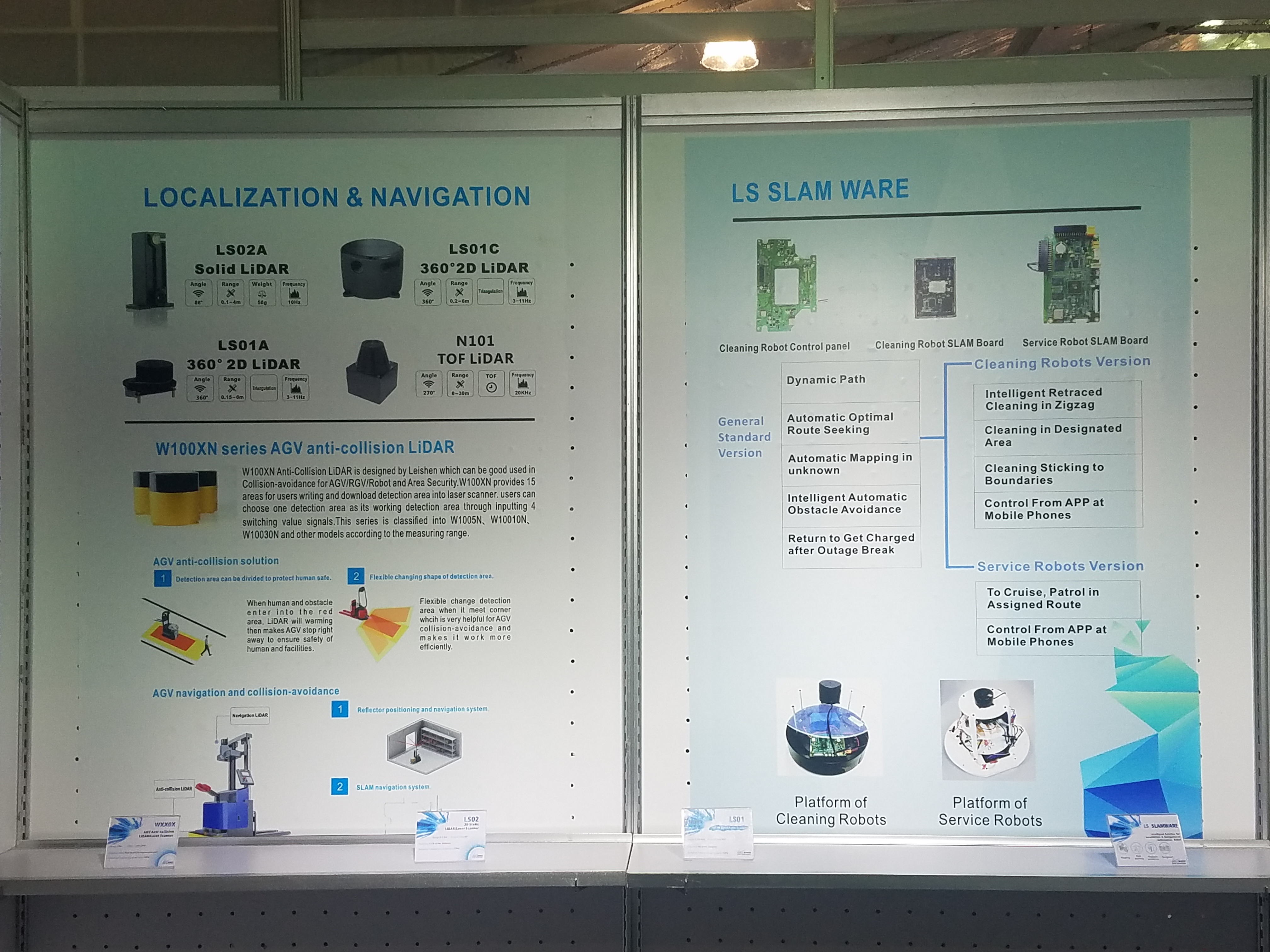
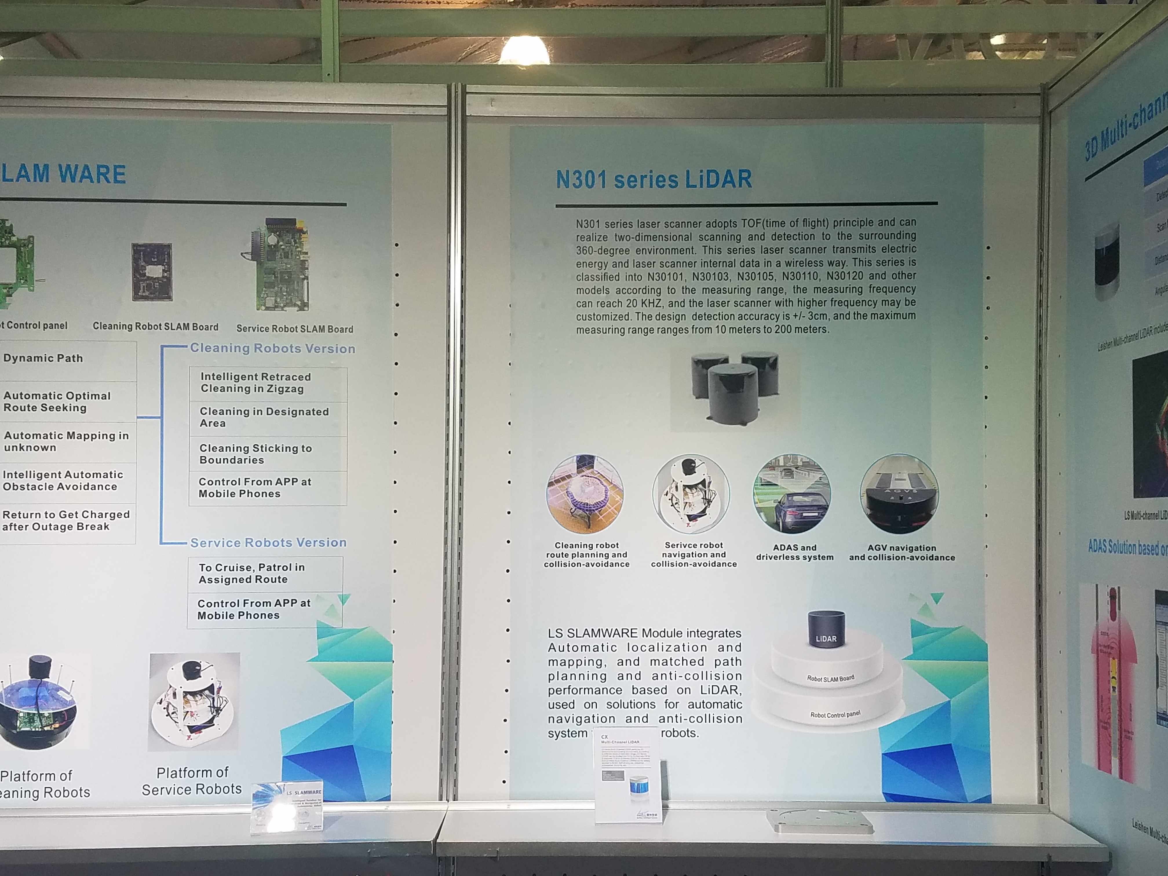
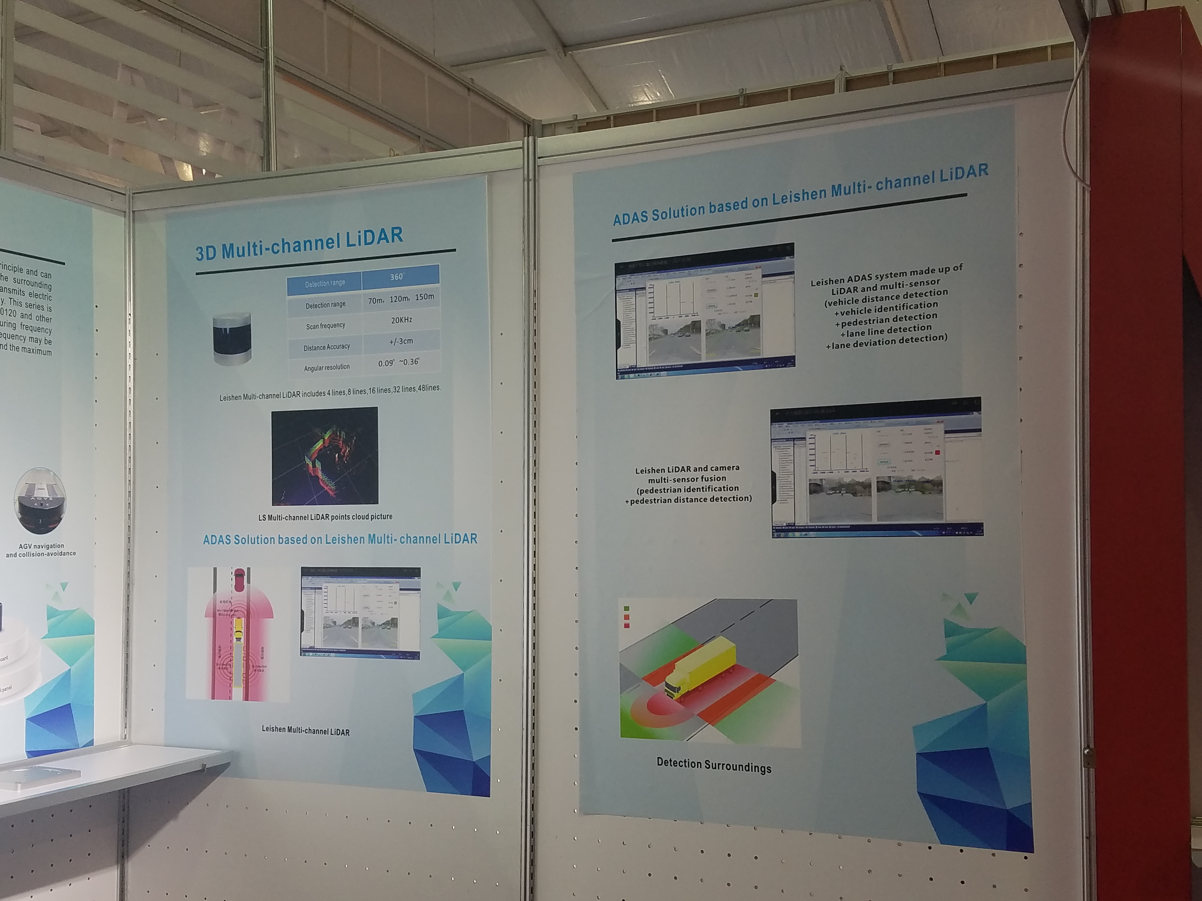
LeiShen Intelligent System Co. Ltd
They were advertising a multi-channel LiDAR with any of 2/4/8/16/32/48 layers.
They also have 2D LiDARs for mobile robot navigation, a solid-state LiDAR that sounds a bit like a TOF camera, and an embedded SLAM solution.
Website: en.leishen-lidar.com
|
|
Fig. 10: |
Fig. 11: |
|
|
Fig. 13: |
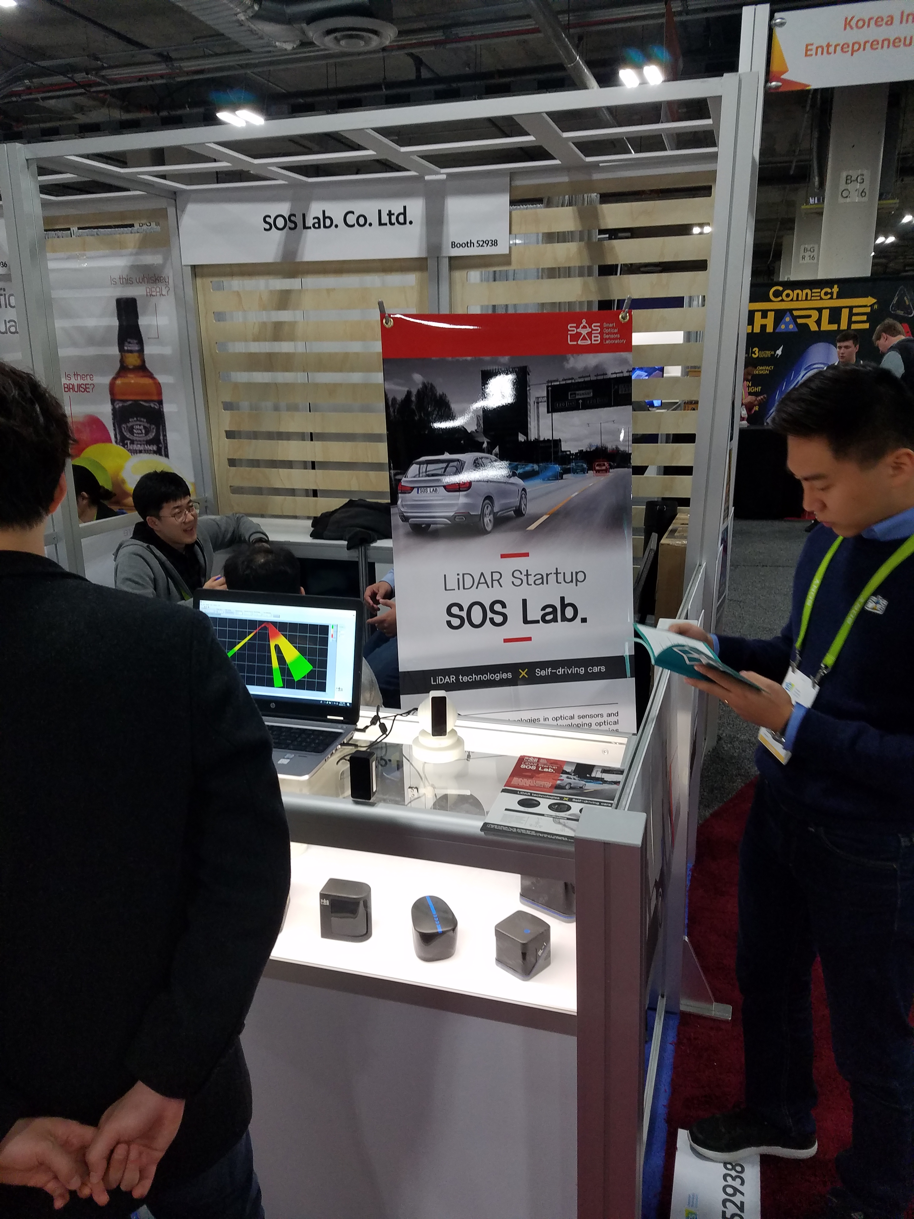
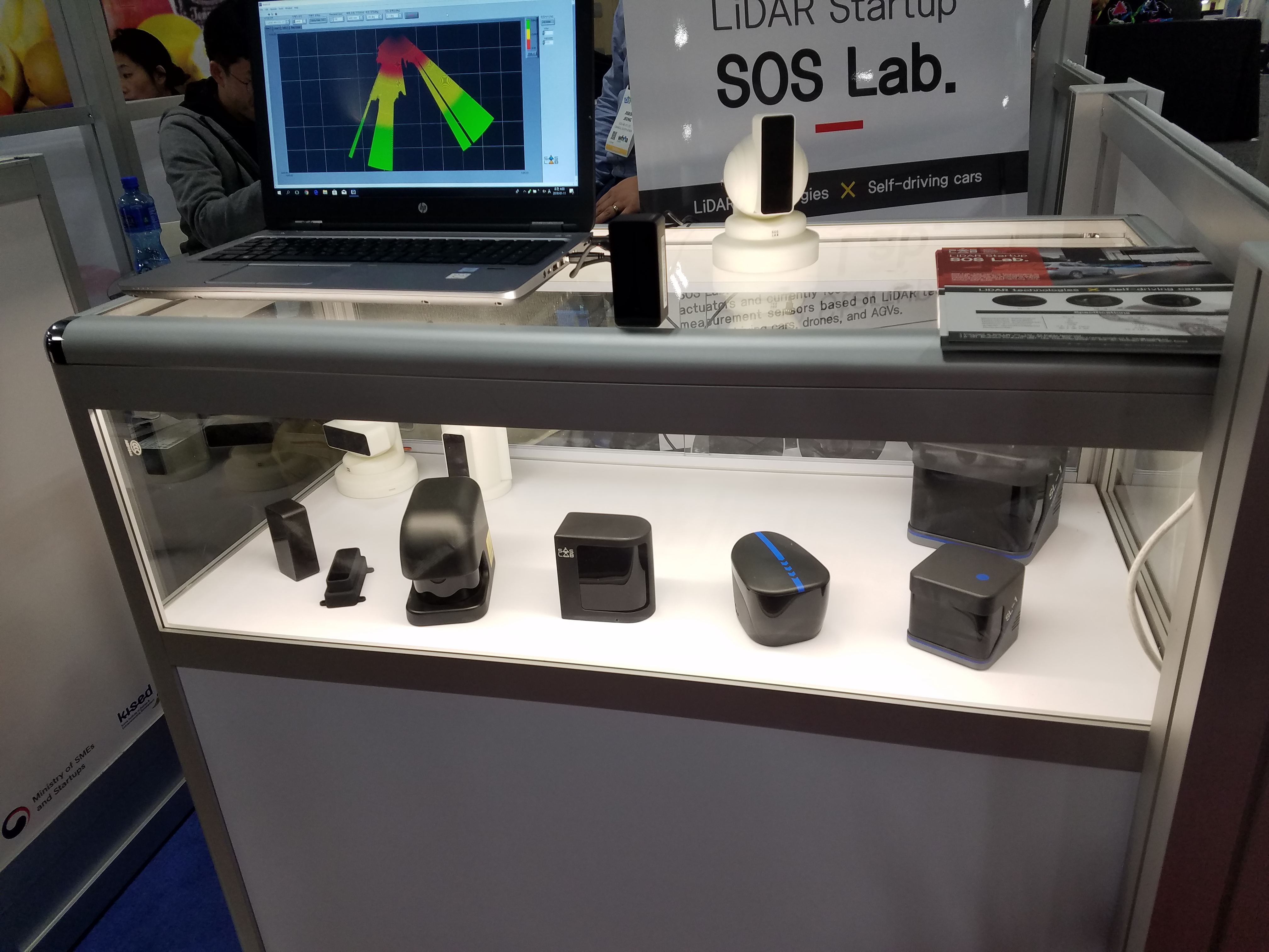
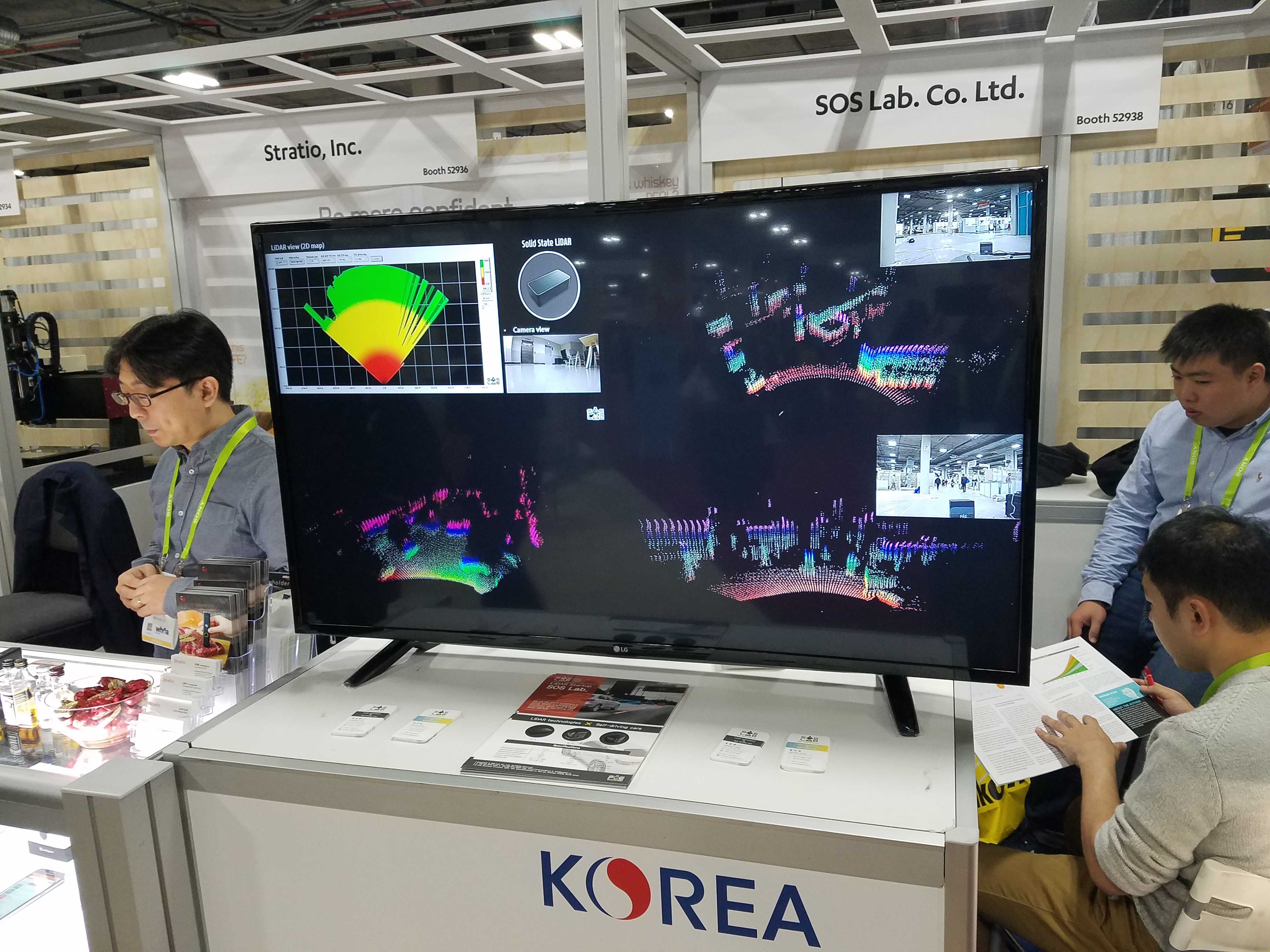
SOS Lab Co. Ltd.
This startup company is developing various prototype LiDAR sensors.
Currently they only have one product which is a 2D planar scanning LiDAR.
Website: www.soslab.co
|
Fig. 14: |
Fig. 15: |
Fig. 16: |
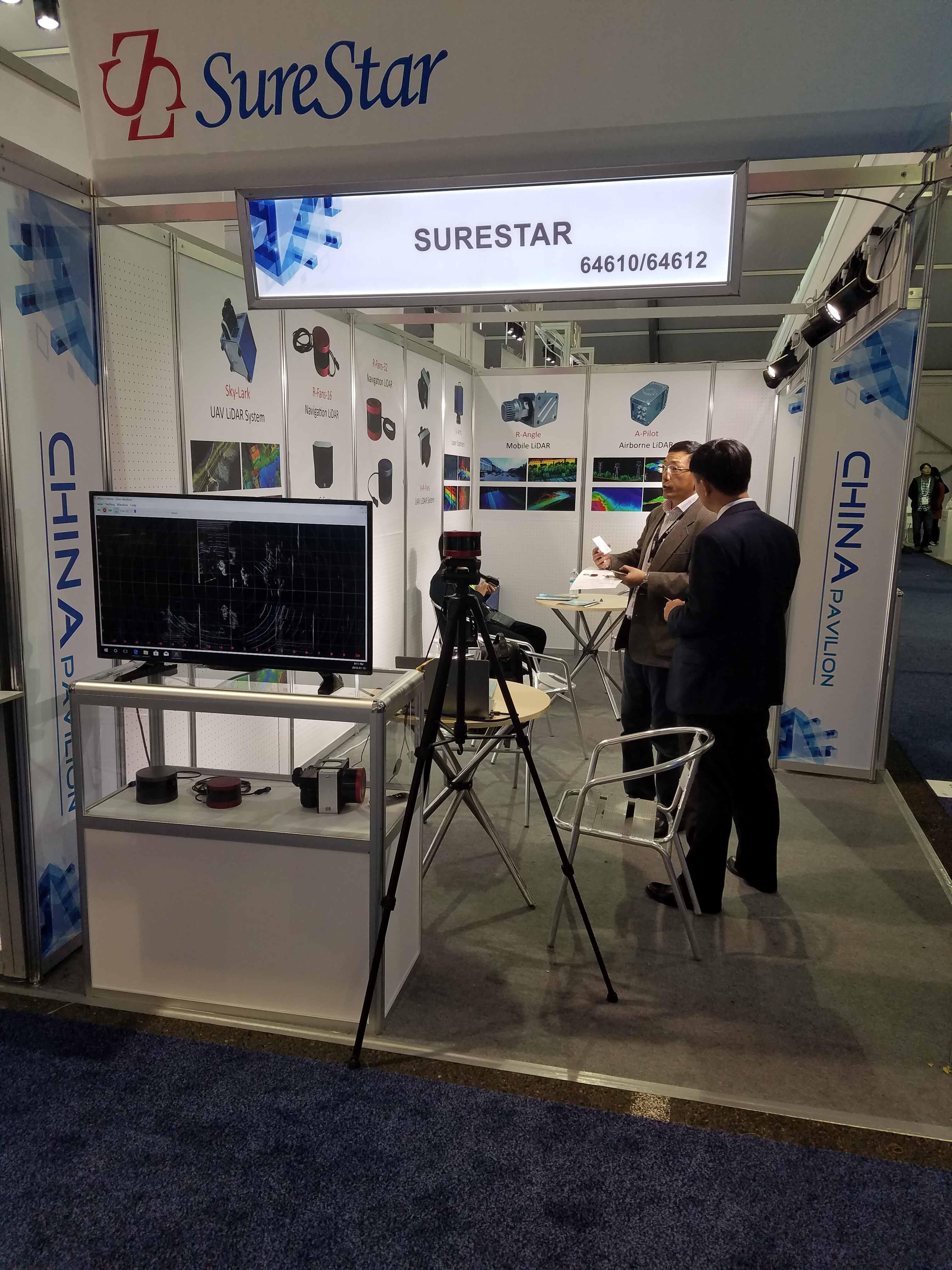
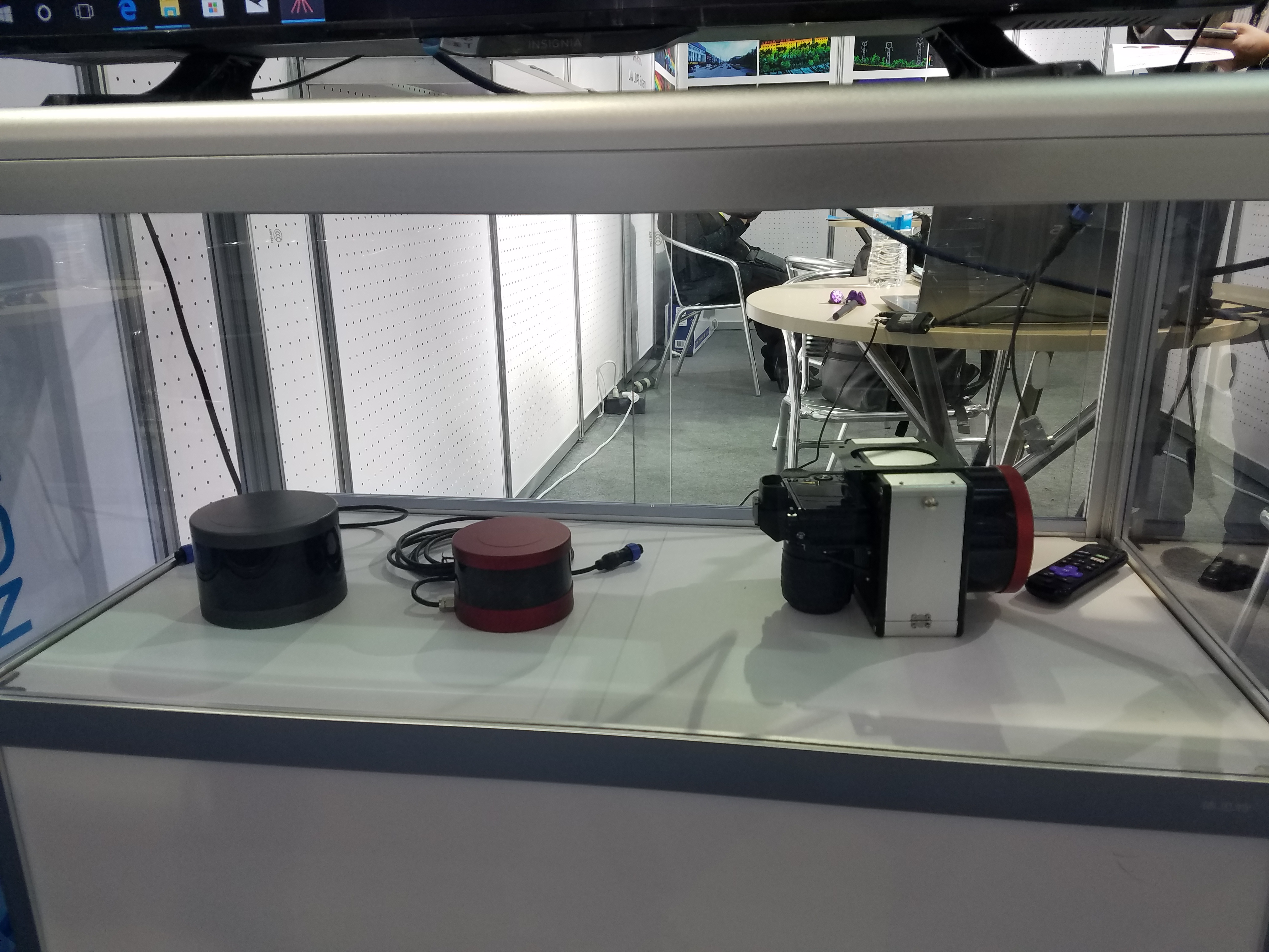
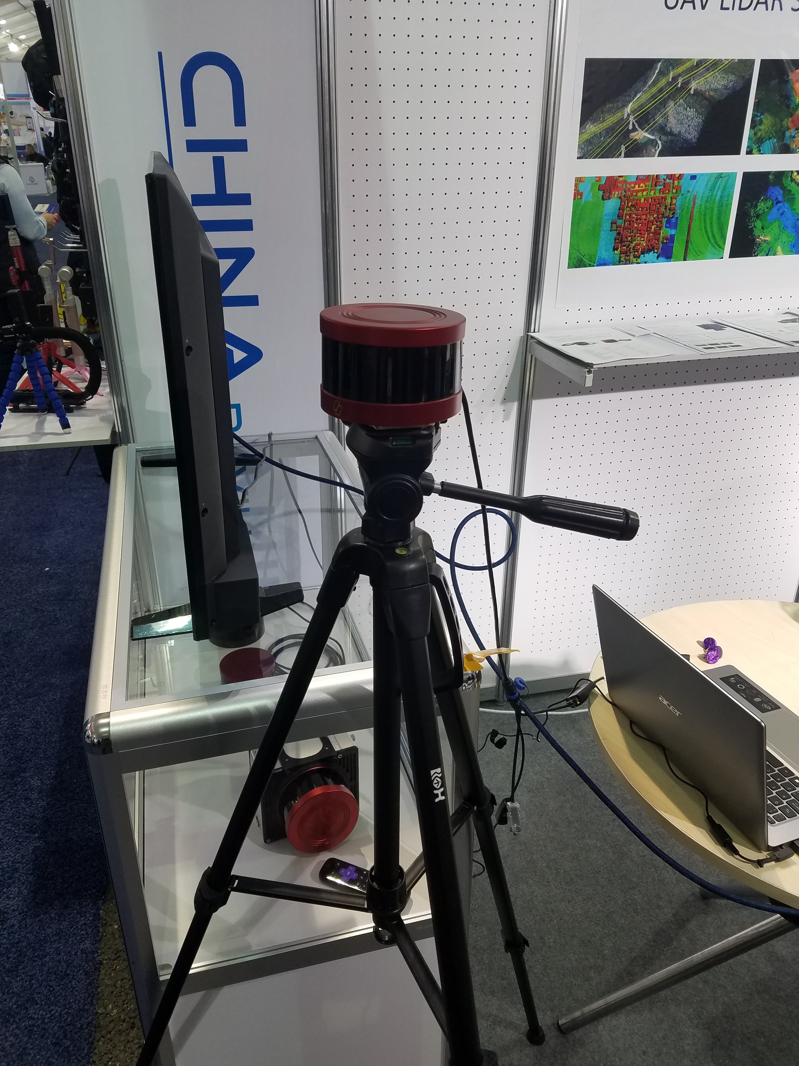
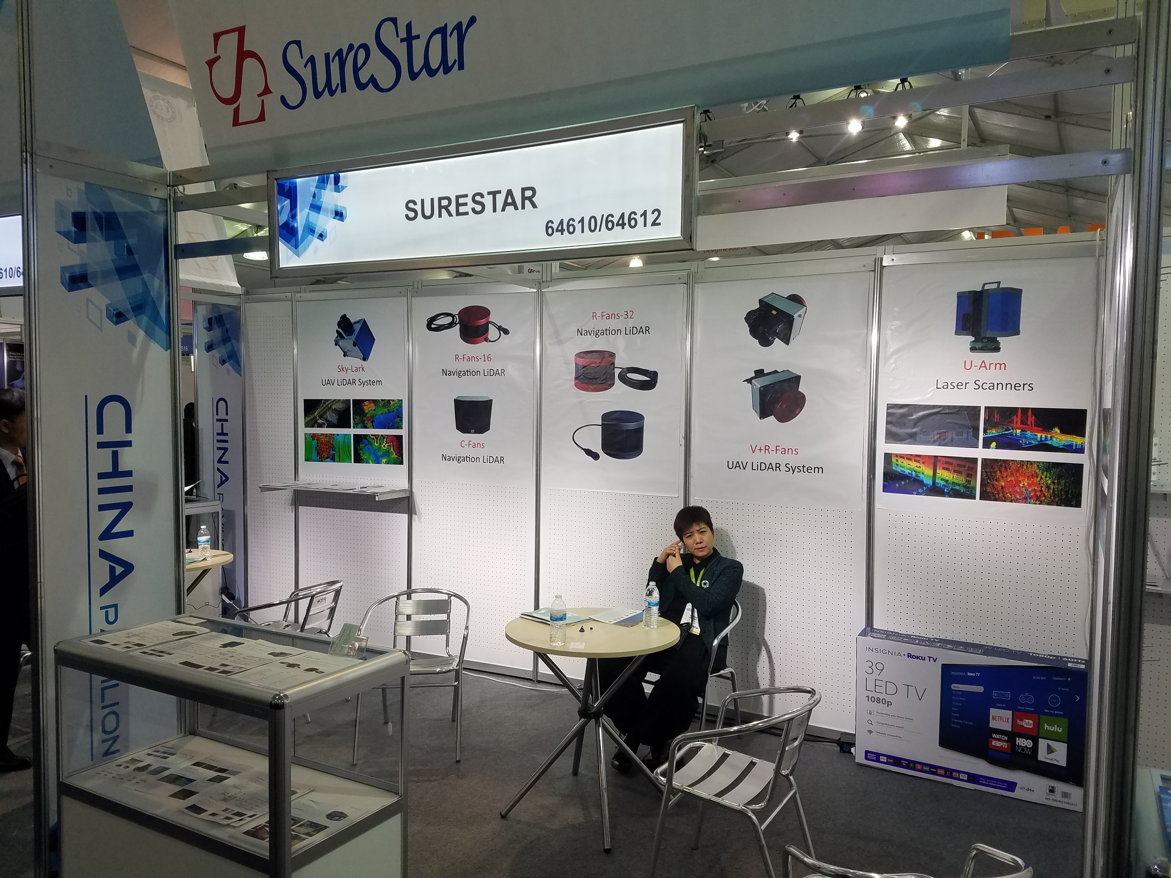
Beijing Surestar Technology Co. Ltd
This company makes LiDAR sensors for mobile surveys (a product called “R-Angle”), airborne surveys (“A-Pilot”) and terrestrial survey applications (“U-Arm”).
It’s interesting that all their sensors look (on the outside) very similar to products made by Velodyne, Riegl and Faro.
However, apparently the internal design is quite different. They use surface-mount components for faster manufacturing, whereas Velodyne still use multiple through-hole PCBs.
And they only spin the mirror, so they can output much higher frequency than Velodyne sensors.
They have a “puck” style LiDAR called “R-Fans”, with 16-channel or 32-channels.
Another model has 32-channels, is designed for long-distance sensing, and has a black-colored housing.
And a 64-channel forward-facing automotive LiDAR called “C-Fans”.
Website: www.isurestar.com/en/
|
Fig. 17: |
Fig. 18: |
Fig. 19: |
|
Fig. 20: |
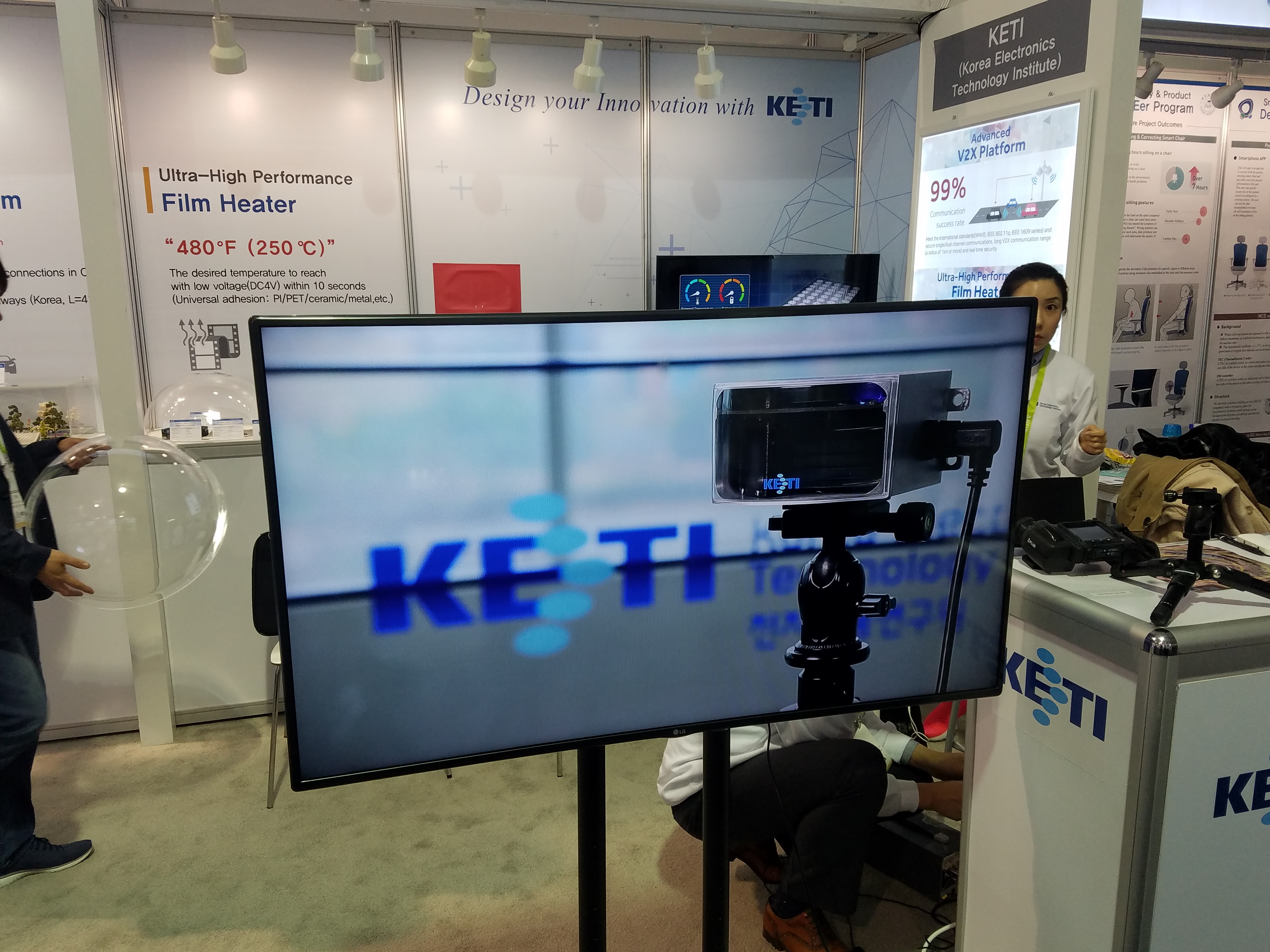
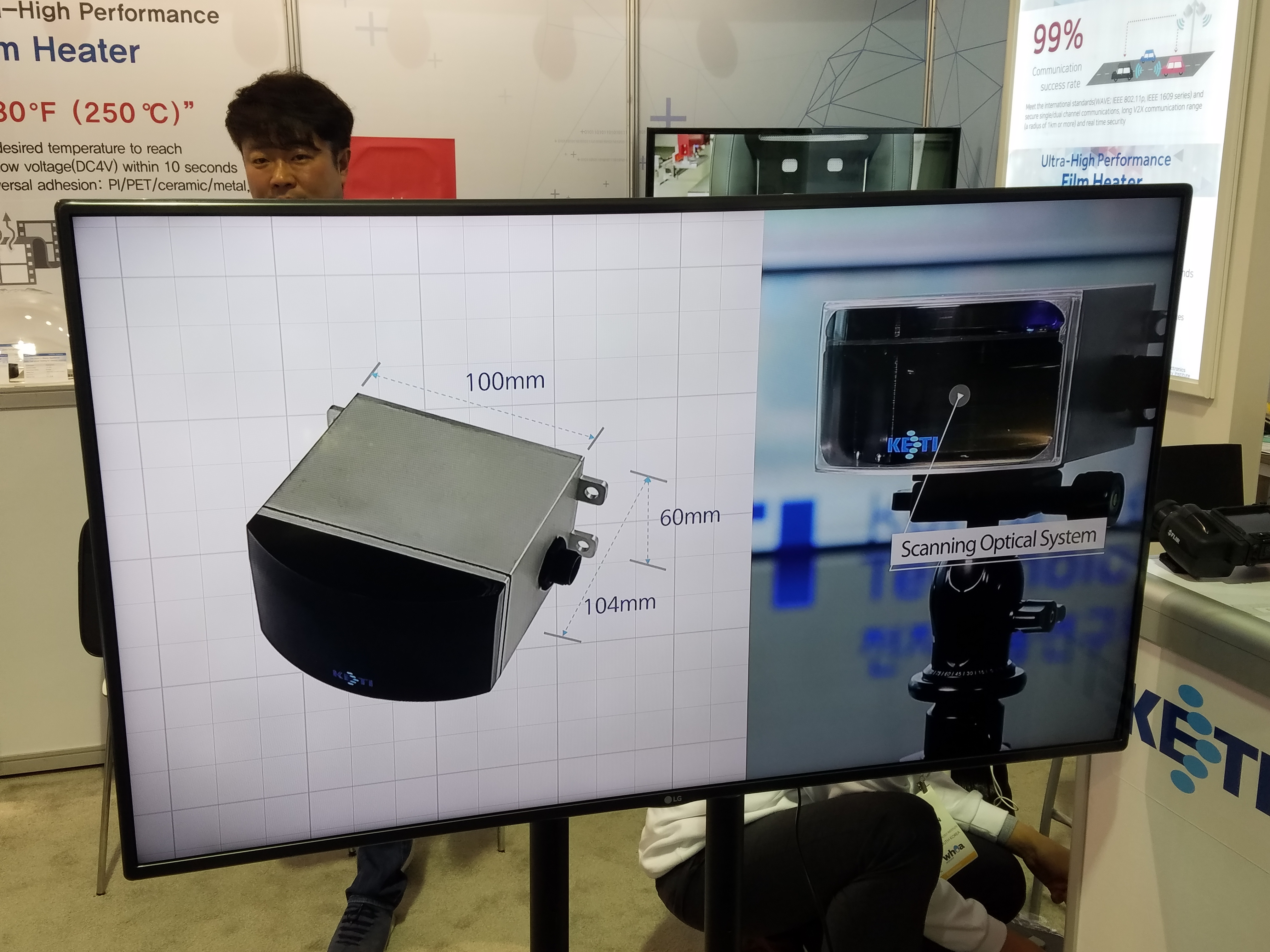
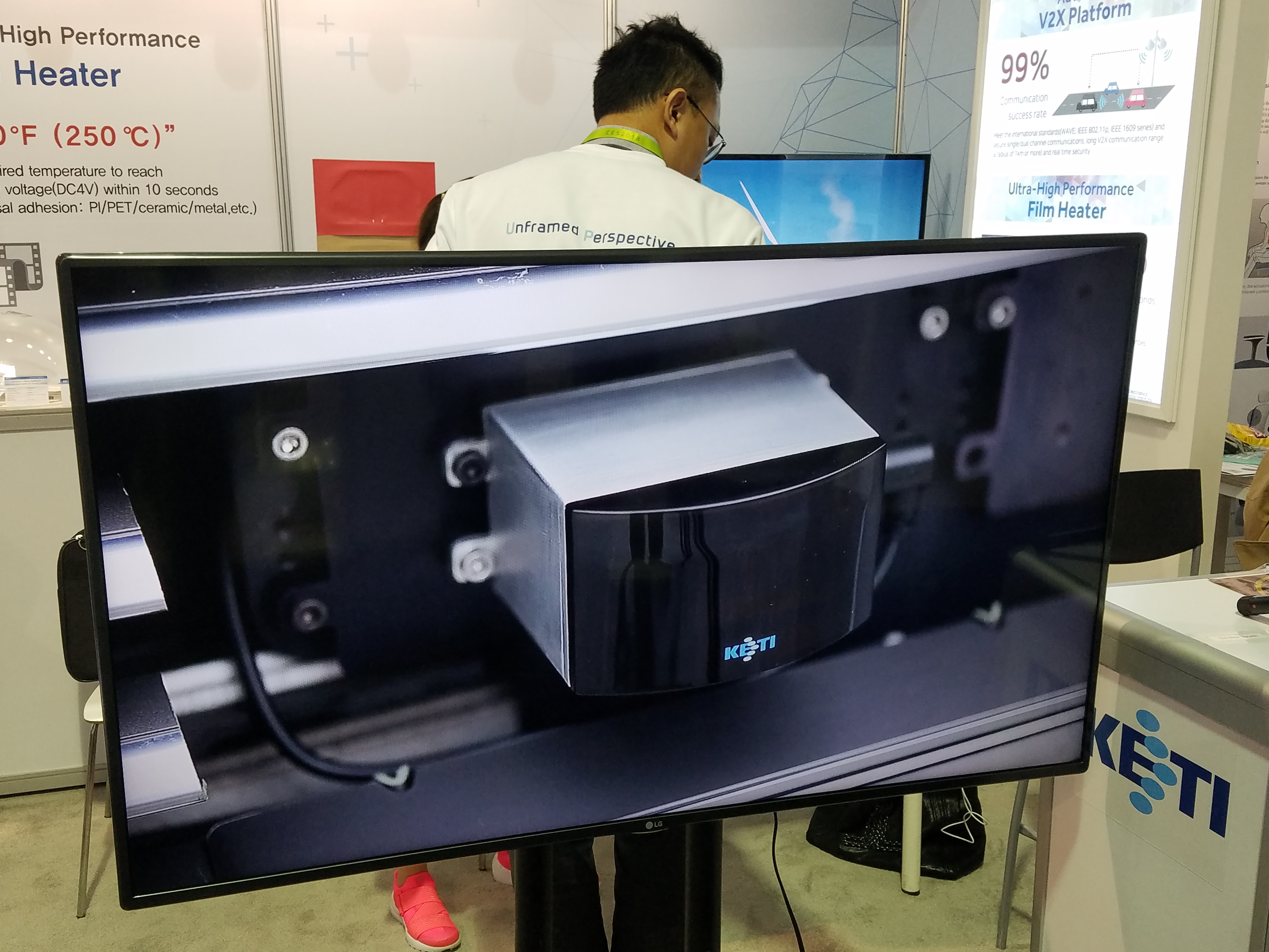
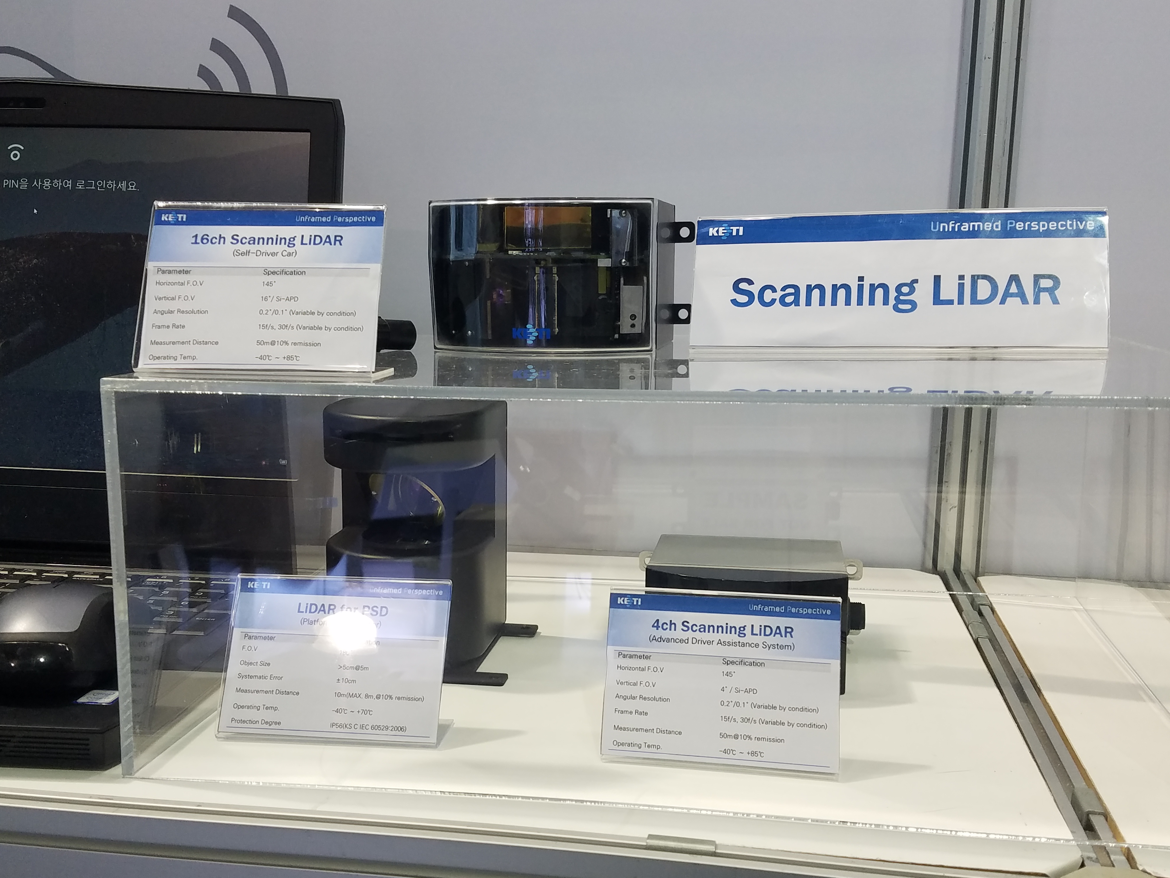
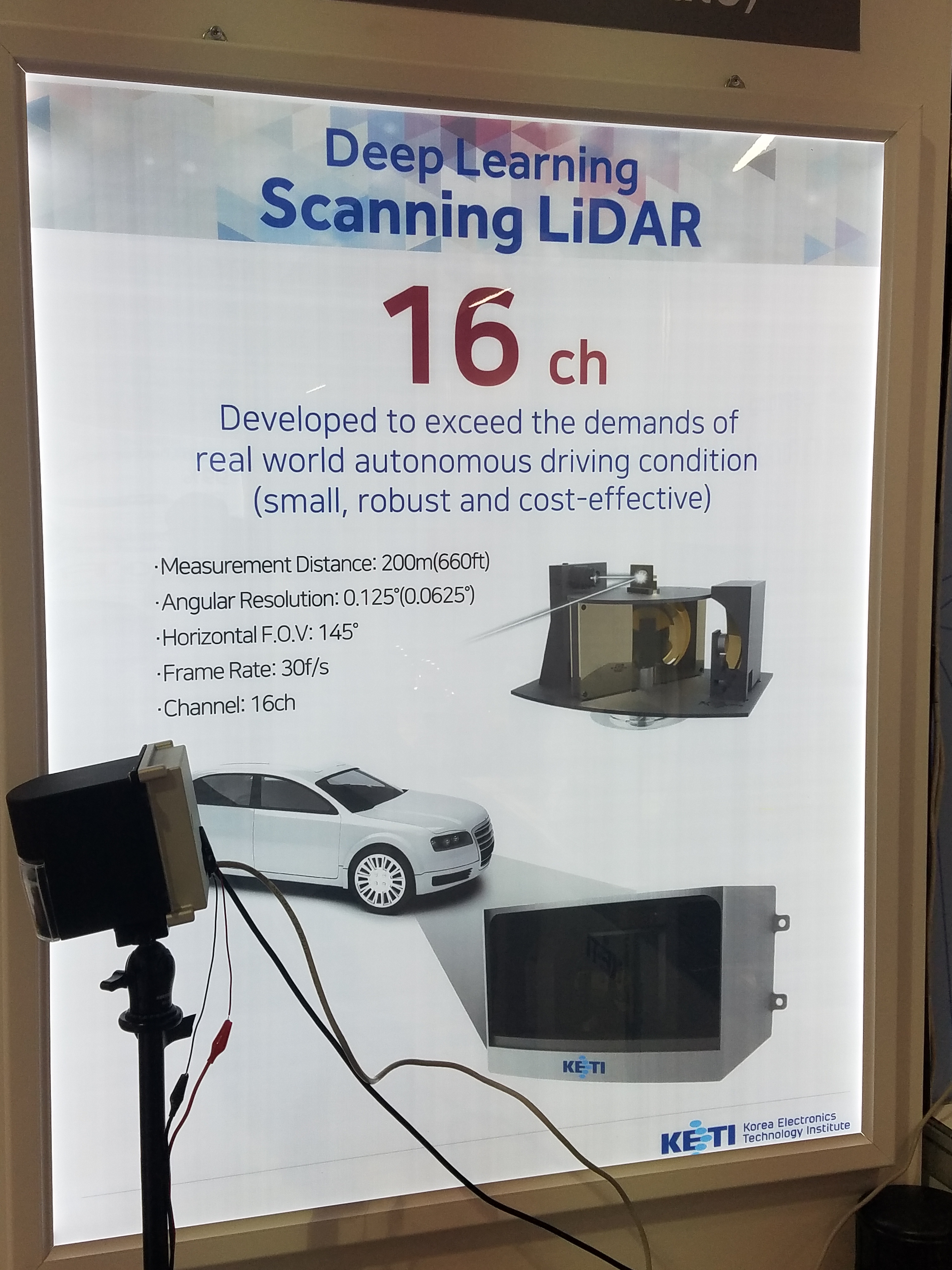
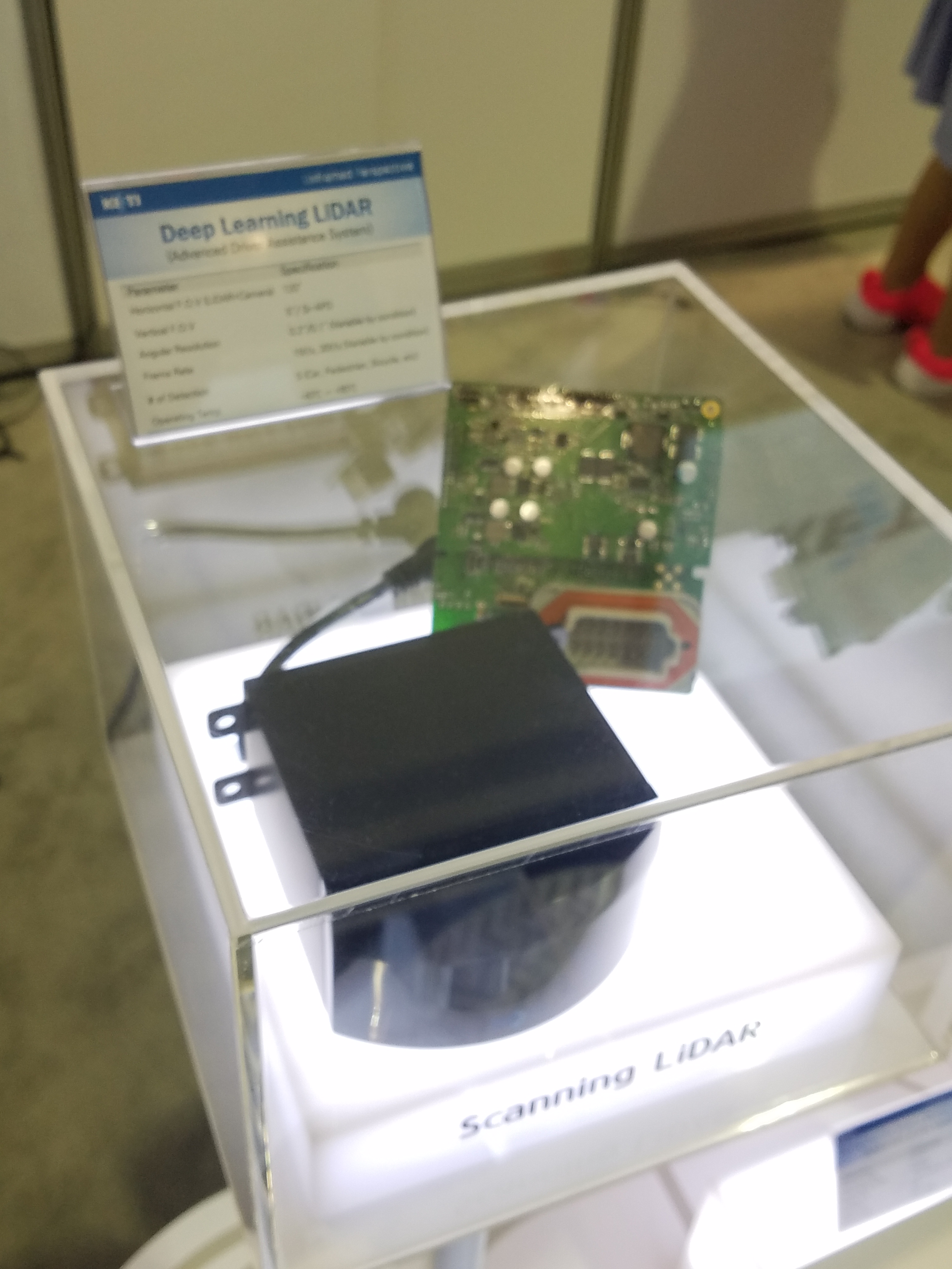
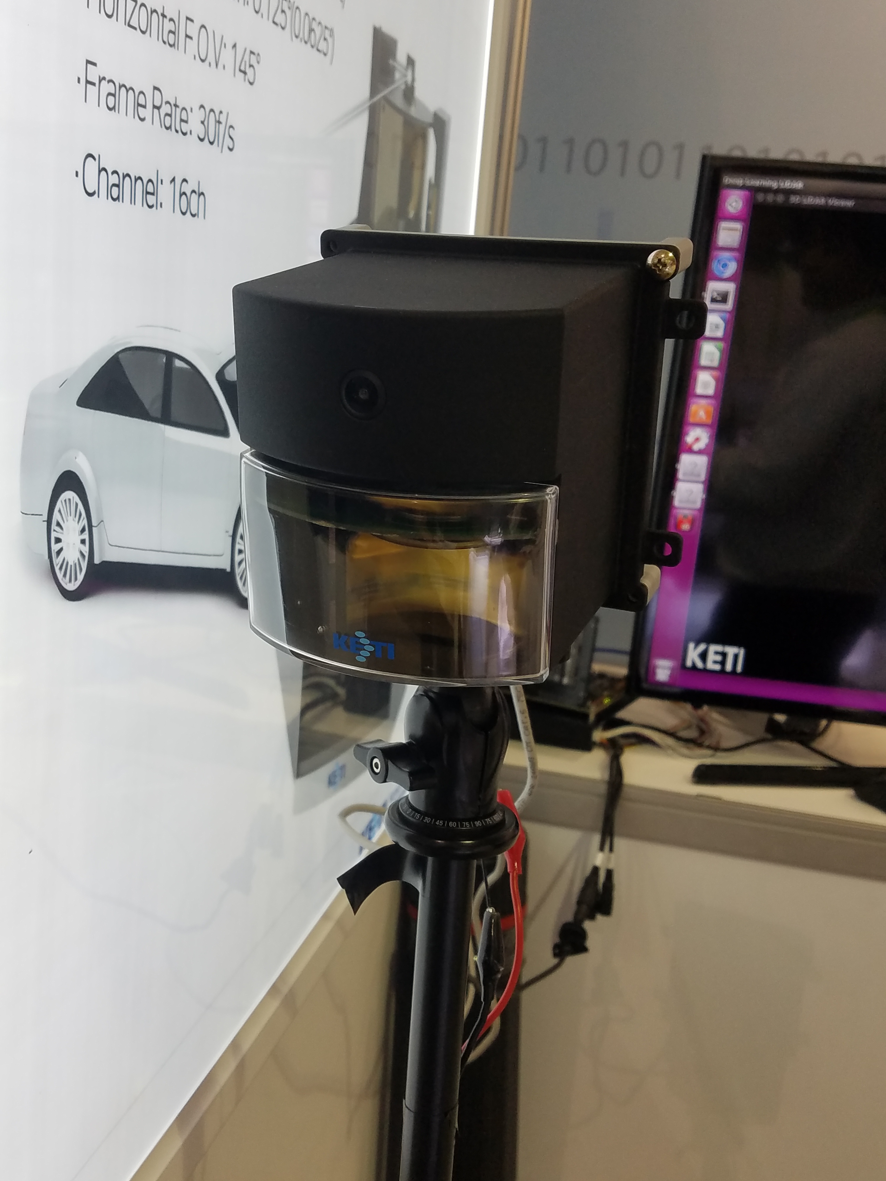
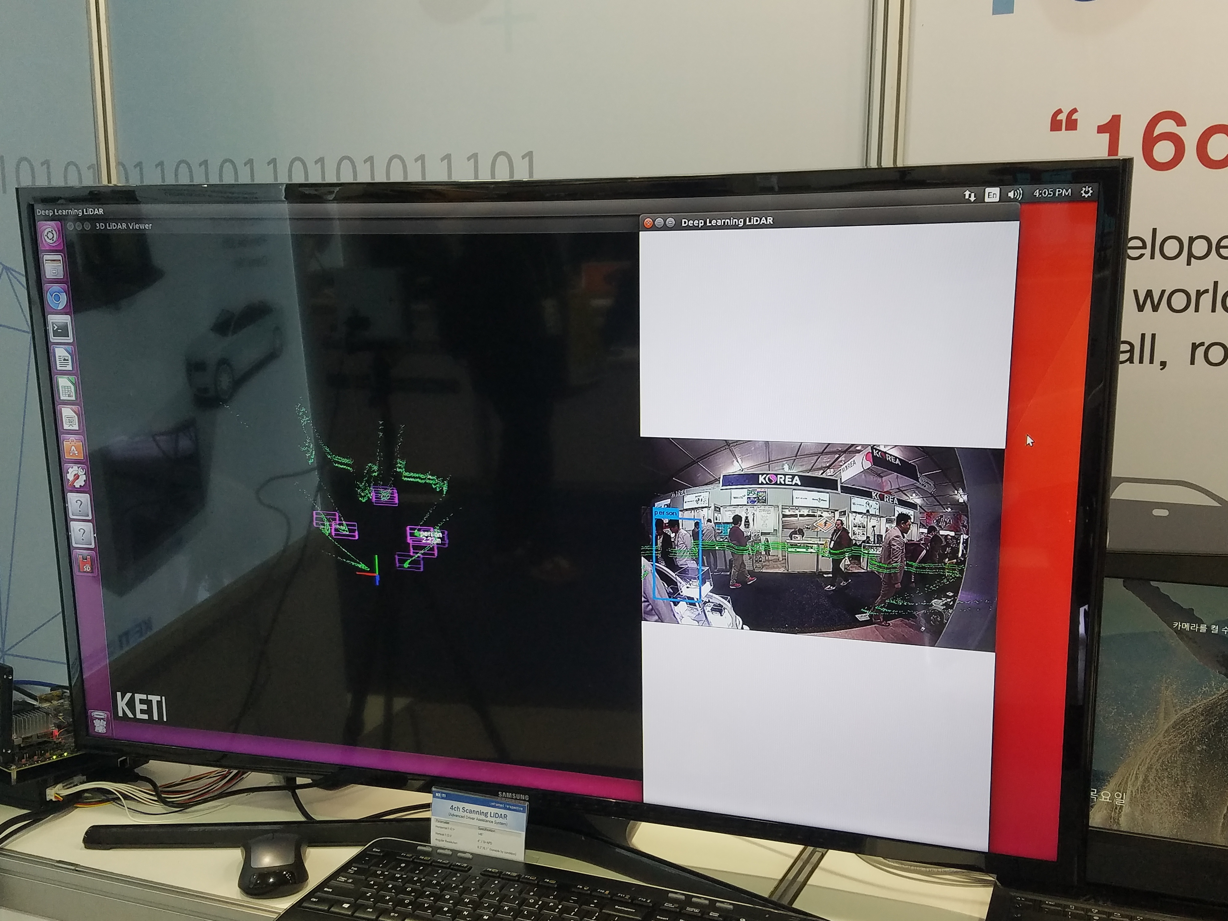
KETI (Korea Electronics Technology Institute)
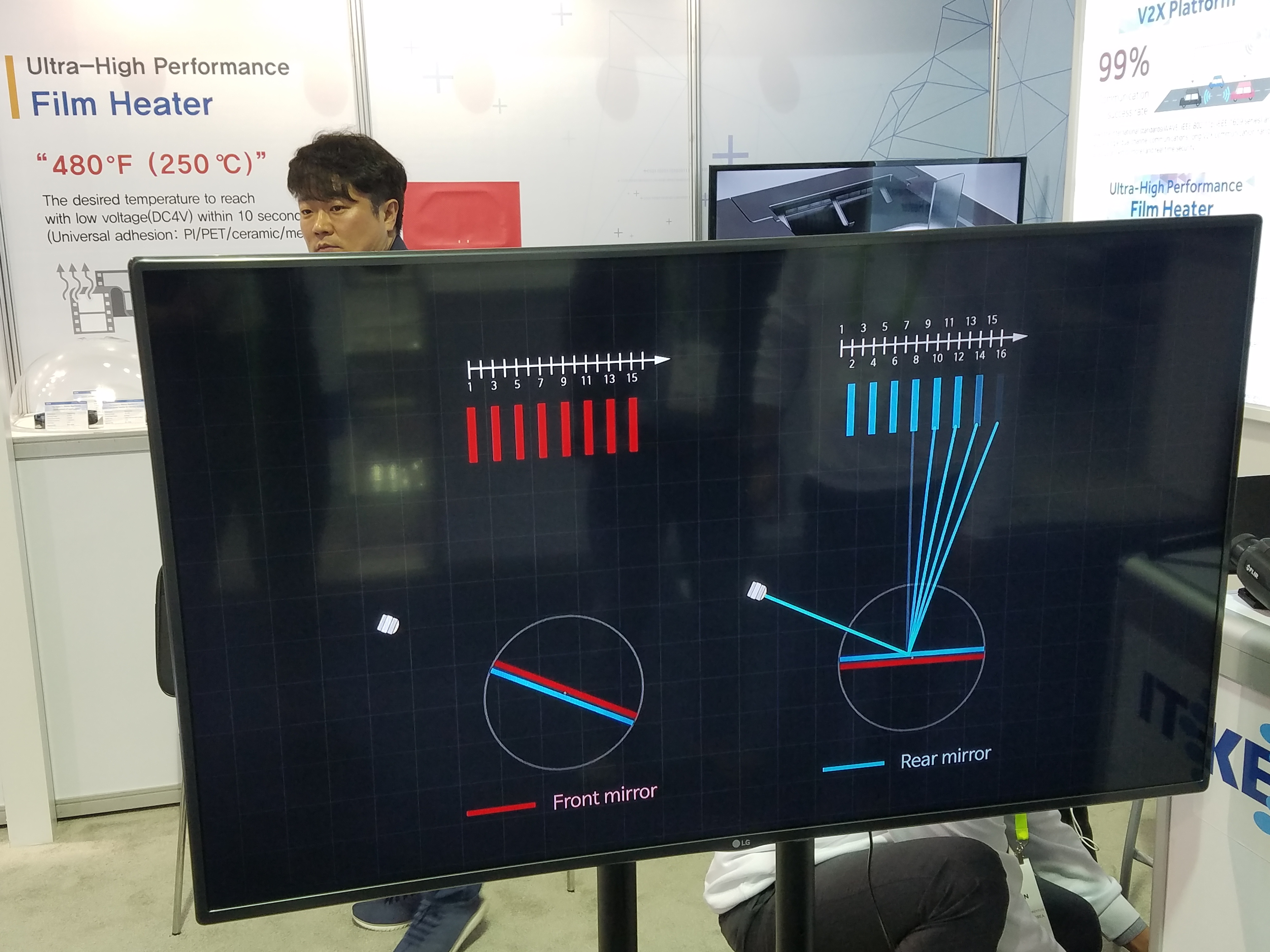
They were showing their prototype scanning LiDAR sensors.
There are different versions with 4 or 16 channels (layers) that all use a mechanically rotating mirror.
There’s also a “Deep Learning Scanning LiDAR” that combines a camera with their 16-ch LiDAR in one package.
Website: www.keti.re.kr/eng/tech/
|
Fig. 21: |
Fig. 22: |
Fig. 23: |
|
Fig. 24: |
Fig. 25: |
Video 5:
Potential applications and overview of their scanner technology. 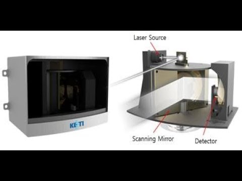 KETI |
|
Fig. 26: |
|
Fig. 28: |
|
Fig. 29: |
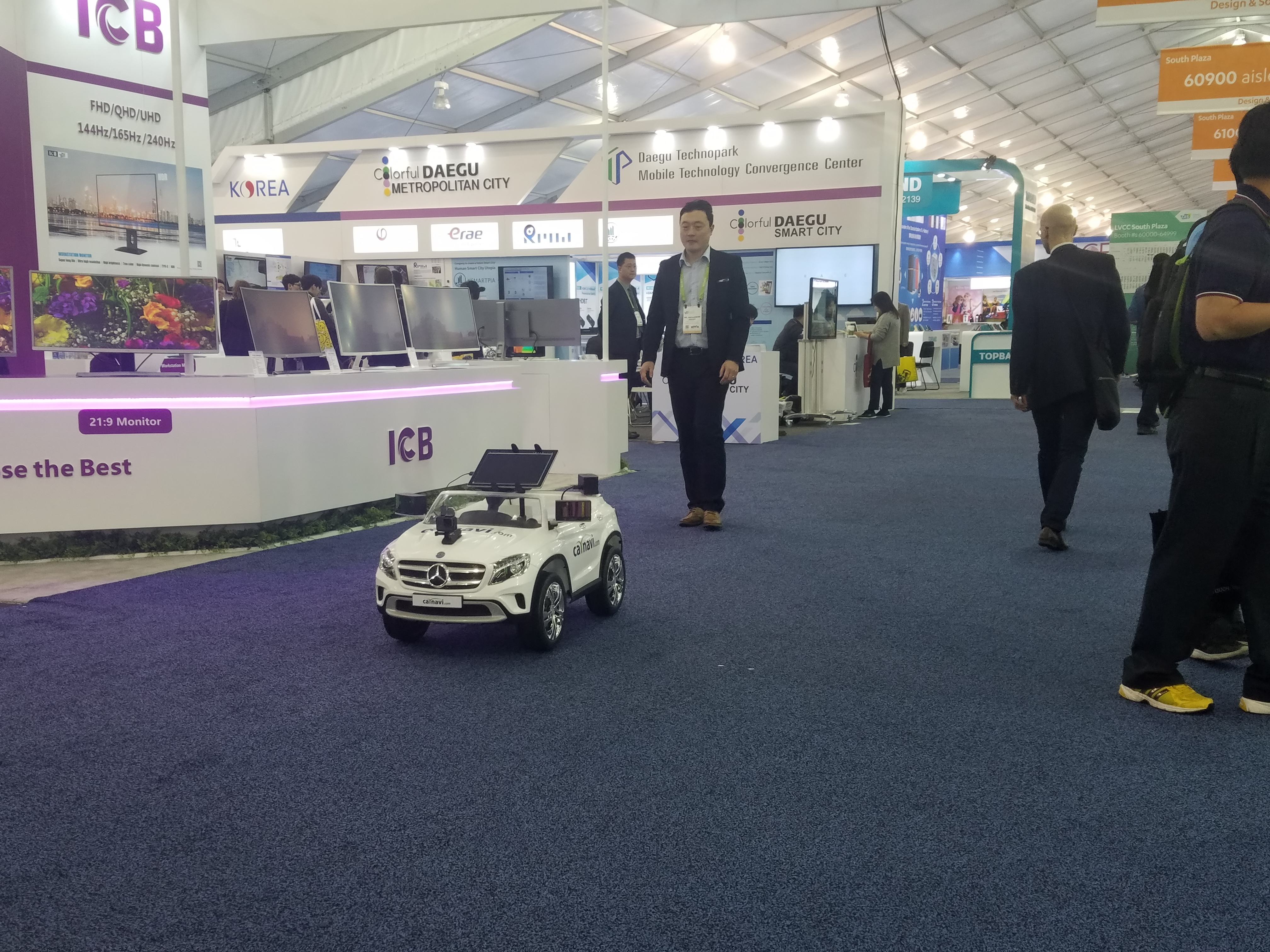
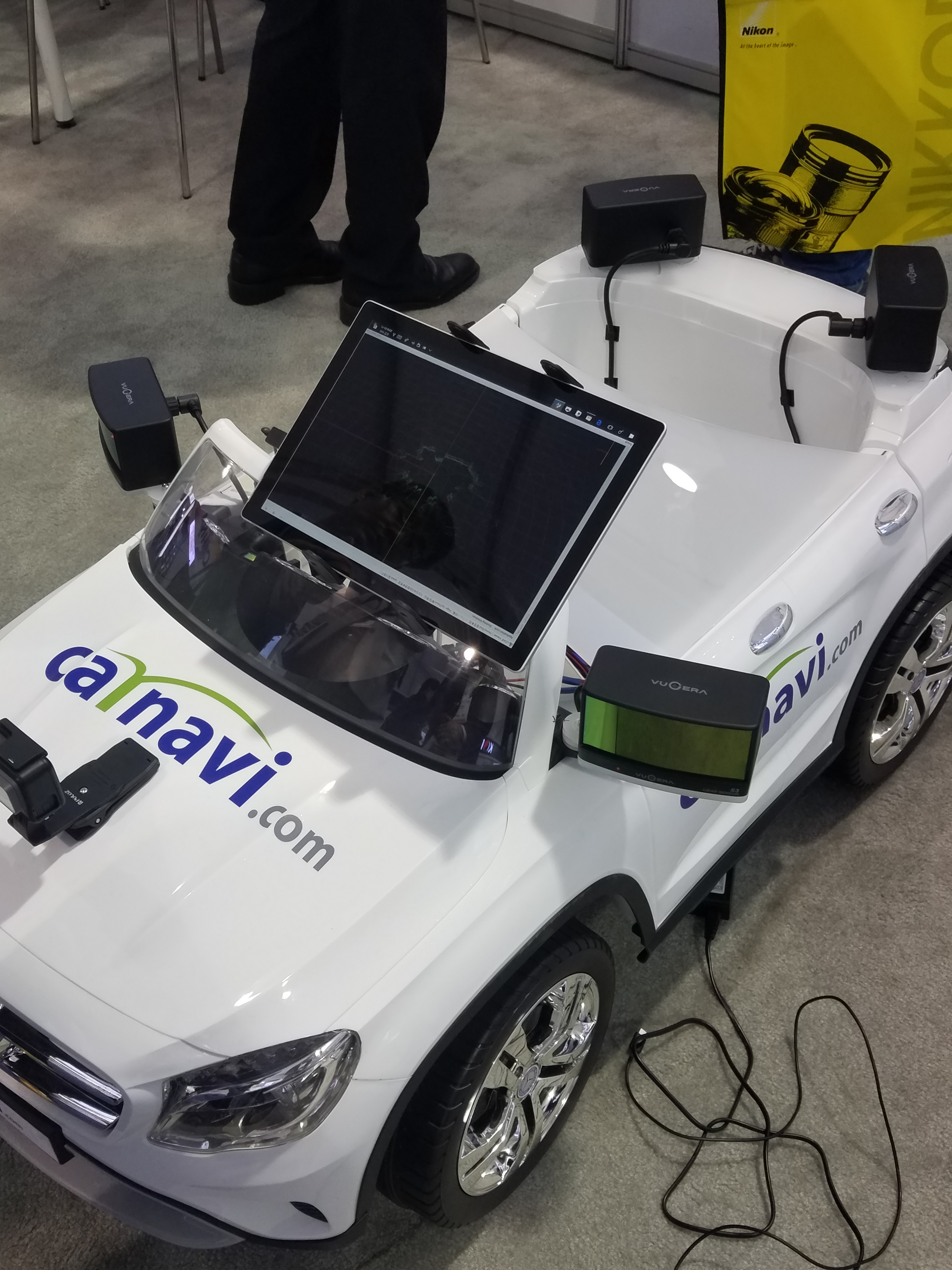
CarNaviCom Co. Ltd
They are commercializing the 4-channel LiDAR developed by KETI (see above).
At their booth they had a cool demo of a small autonomous toy car that was driving around.
It’s a kids ride-on car with a computer and 4 LiDAR sensors arranged in a 360 degree configuration.
The sensors are the Vugera VG-S3 3-channel LiDAR:
www.buykorea.or.kr/self-driving-autonomous-vehicle-lidar-sensor
Website: www.carnavi.com
|
|
Video 6: |
Video 7:
Close-up view of the output from the 4 LiDAR sensors.  Carnavicom |
|
Fig. 31: |

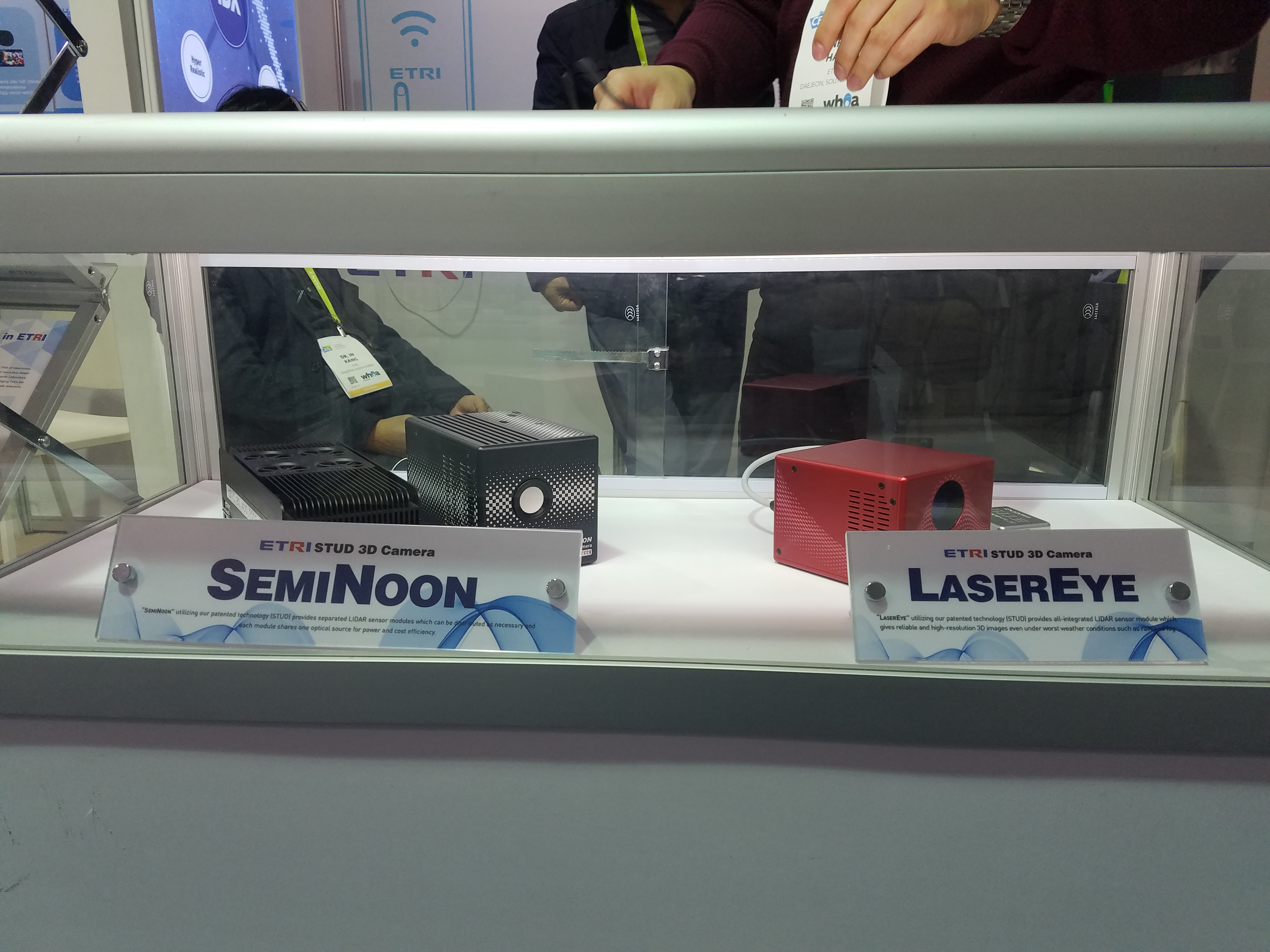
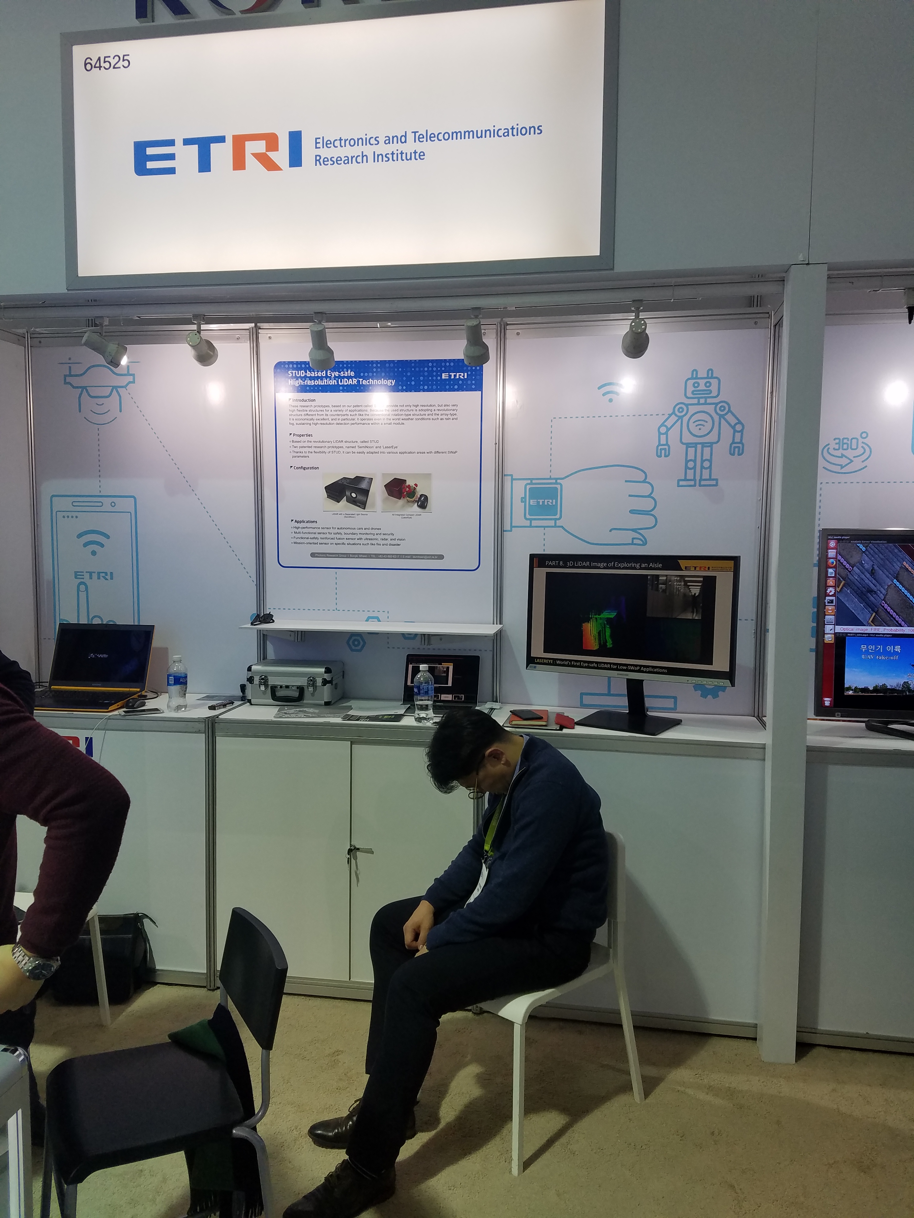
ETRI (Electronics and Telecommunications Research Institute)
They were showing two prototype LiDAR sensors called “SemiNoon” and “LaserEye” which both incorporate their STUD (STatic Unitary Detector) technology.
Unfortunately I wasn’t able to learn what makes this technology different or better to other LiDARs.
Here’s a paper by the group:
Mheen et al., “High-resolution three-dimensional laser radar with static unitary detector”, Electronics Letters 2014 PDF
|
Fig. 32: |
Fig. 33: |
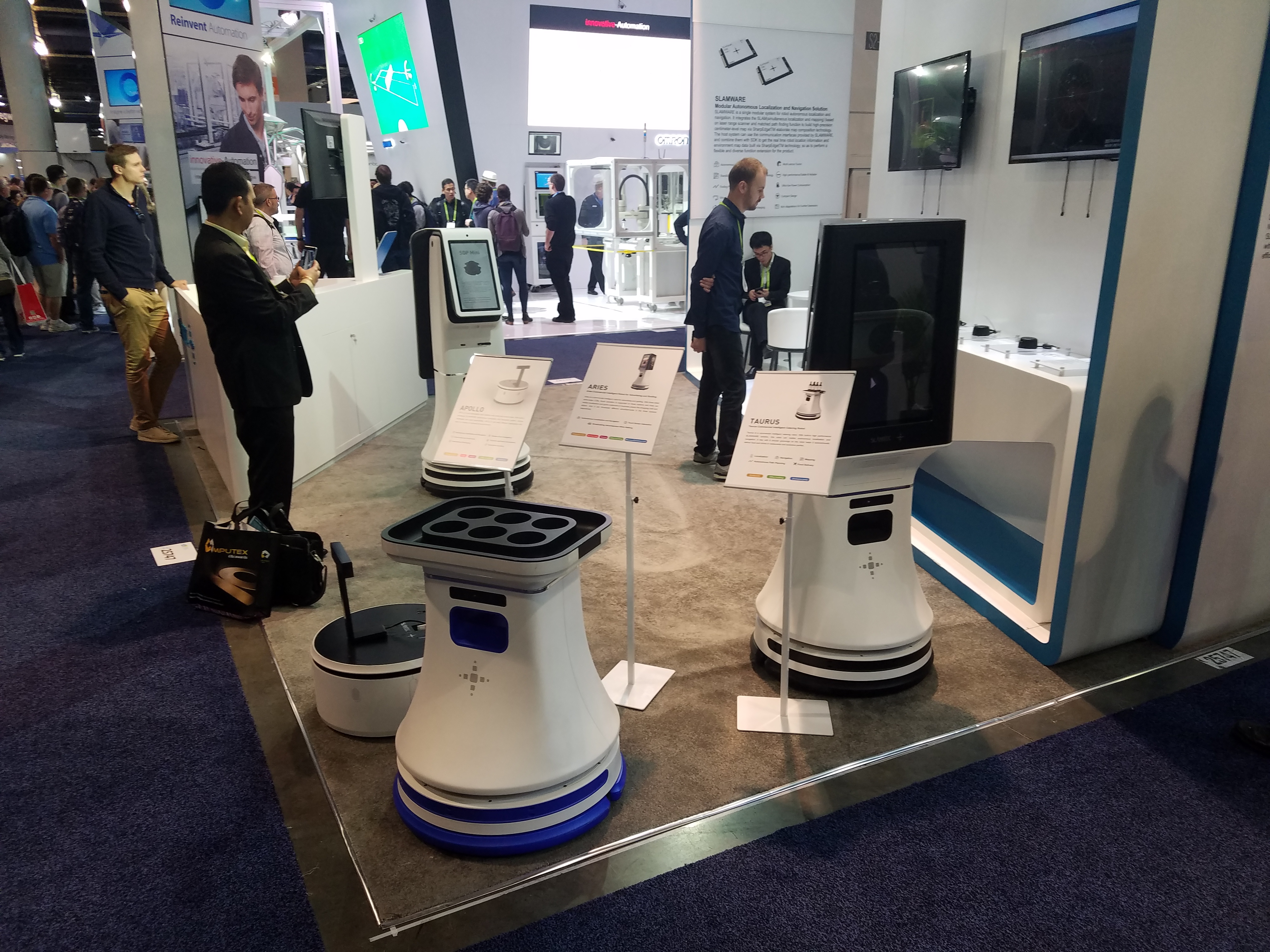
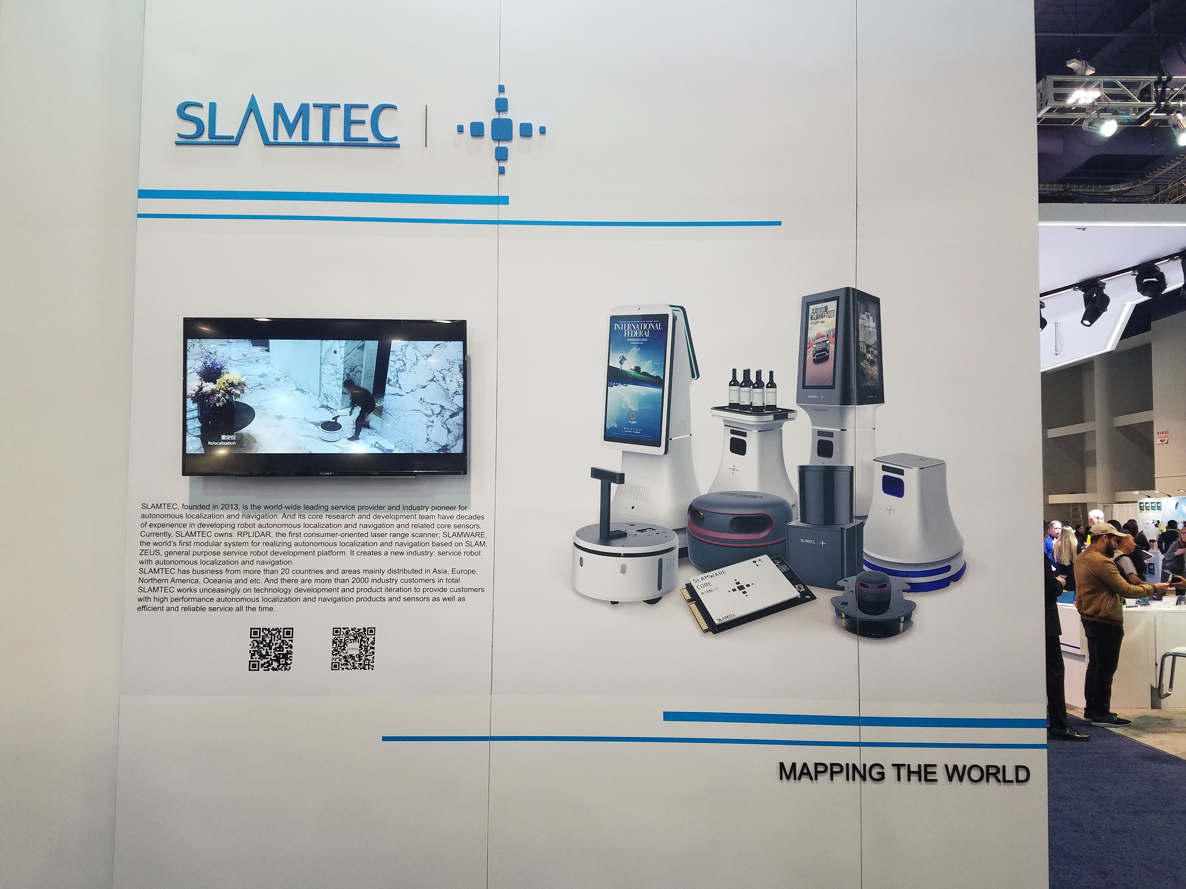
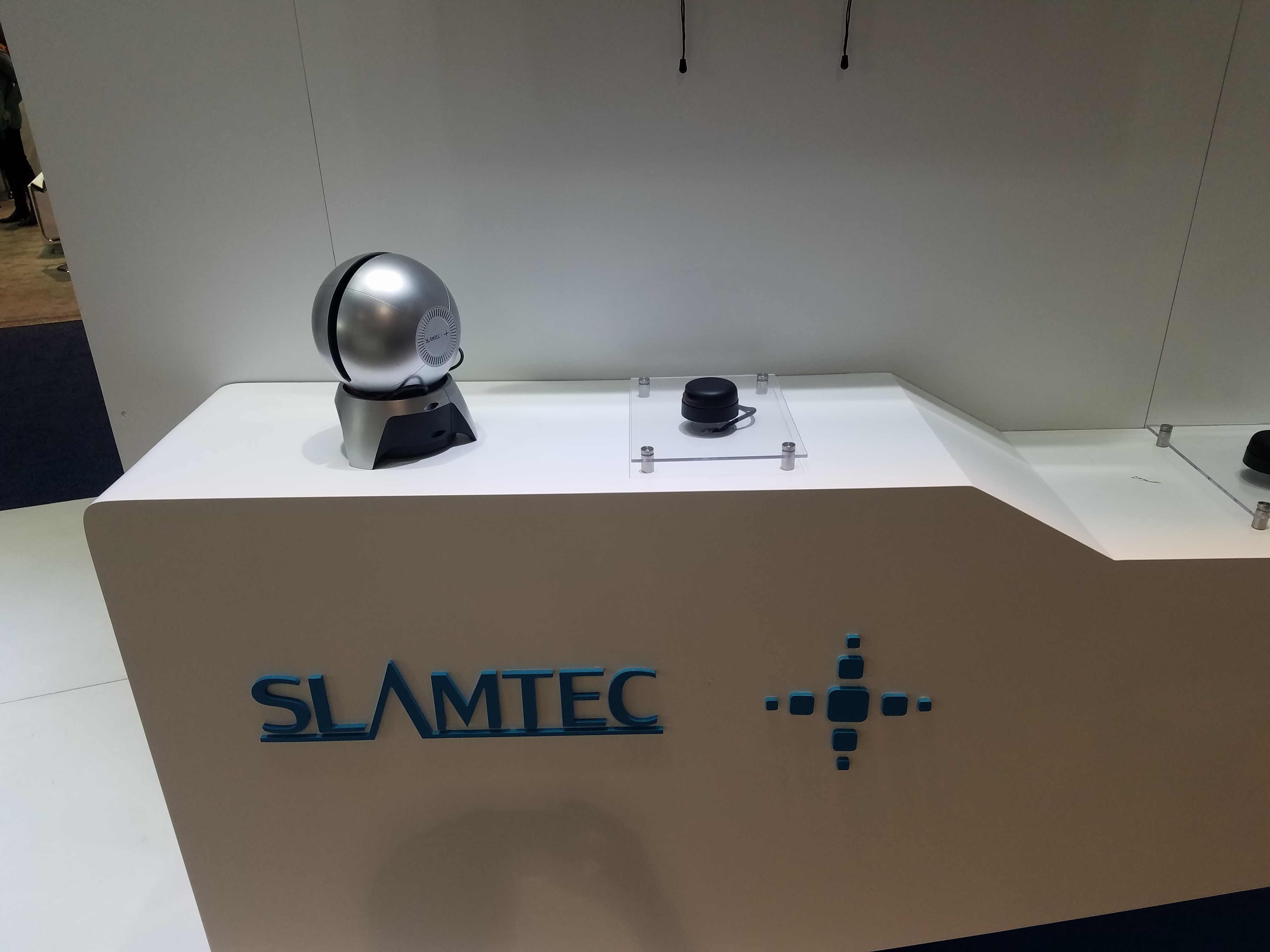
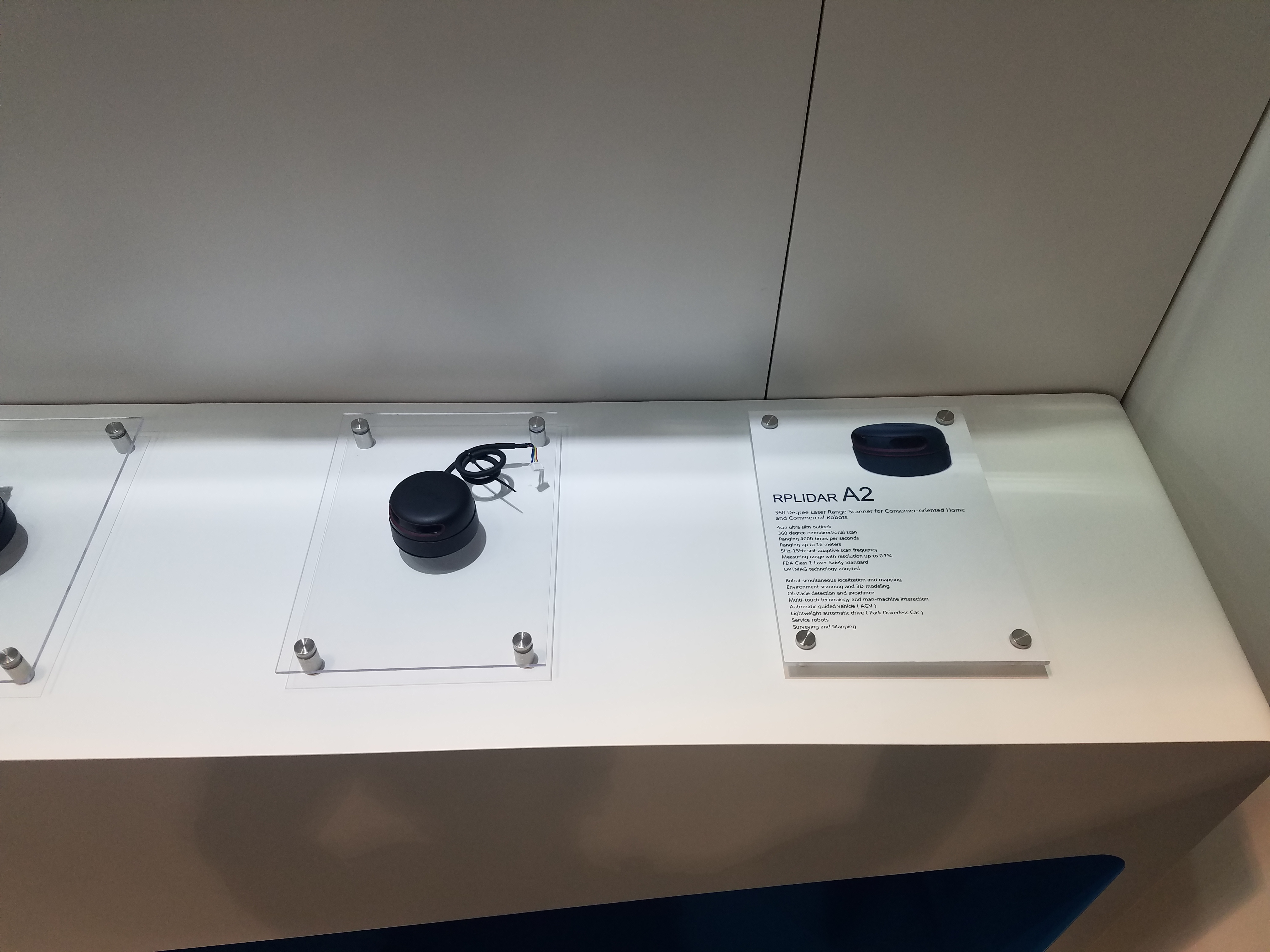
Shanghai Slamtec Co., Ltd
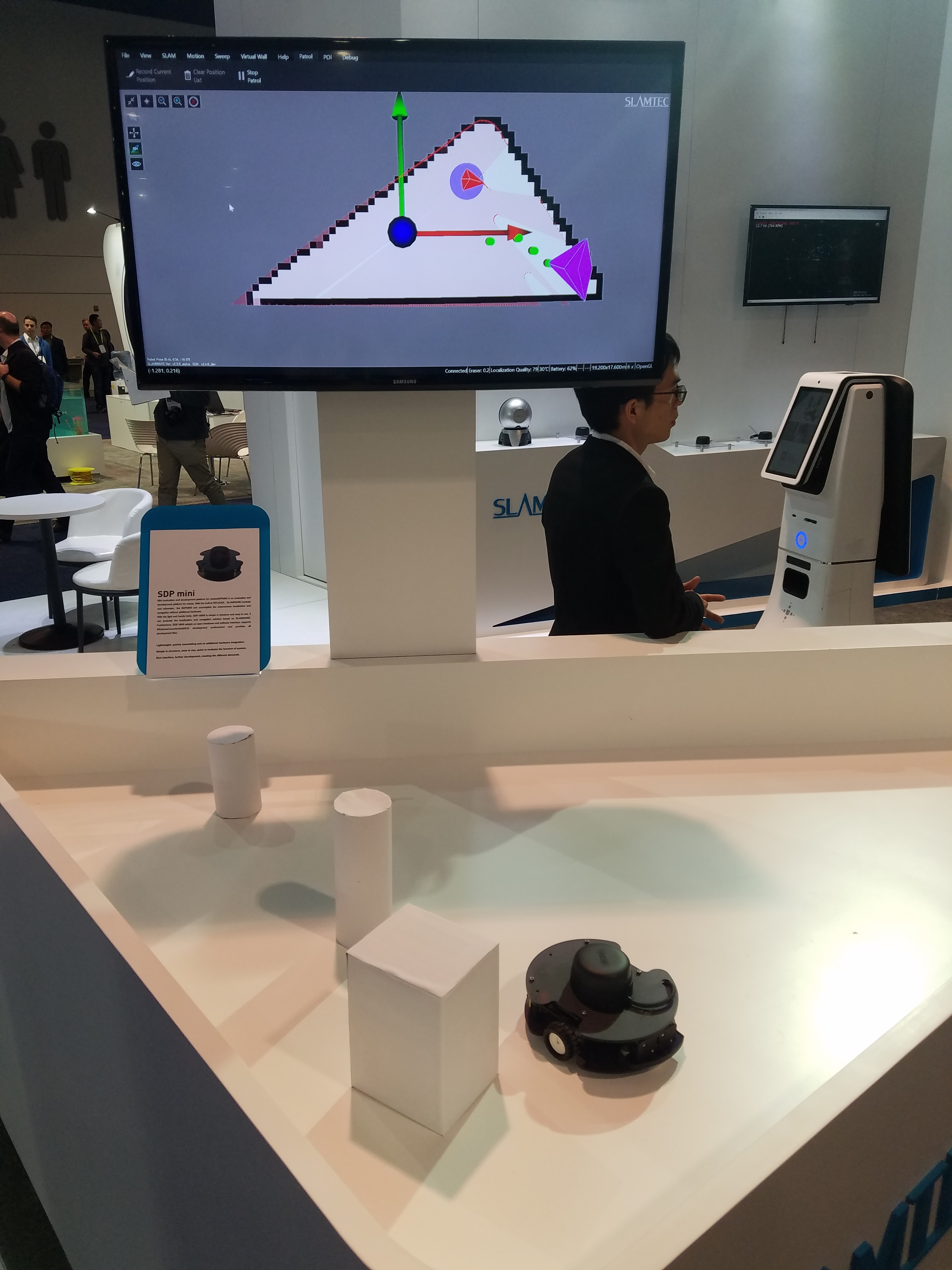
SLAMTEC is known for their RPLiDAR sensor, which was the first low-cost 2D scanning LiDAR for the hobbyist.
It is not in the same class as a Hokuyo 2D LiDAR, however they now have a more expensive model designed for service robots.
Note: The RPLiDAR has a sensor head that rotates a full 360 degrees, compared to the Hokuyo which achieves a 270 degree FOV using a scanning mirror.
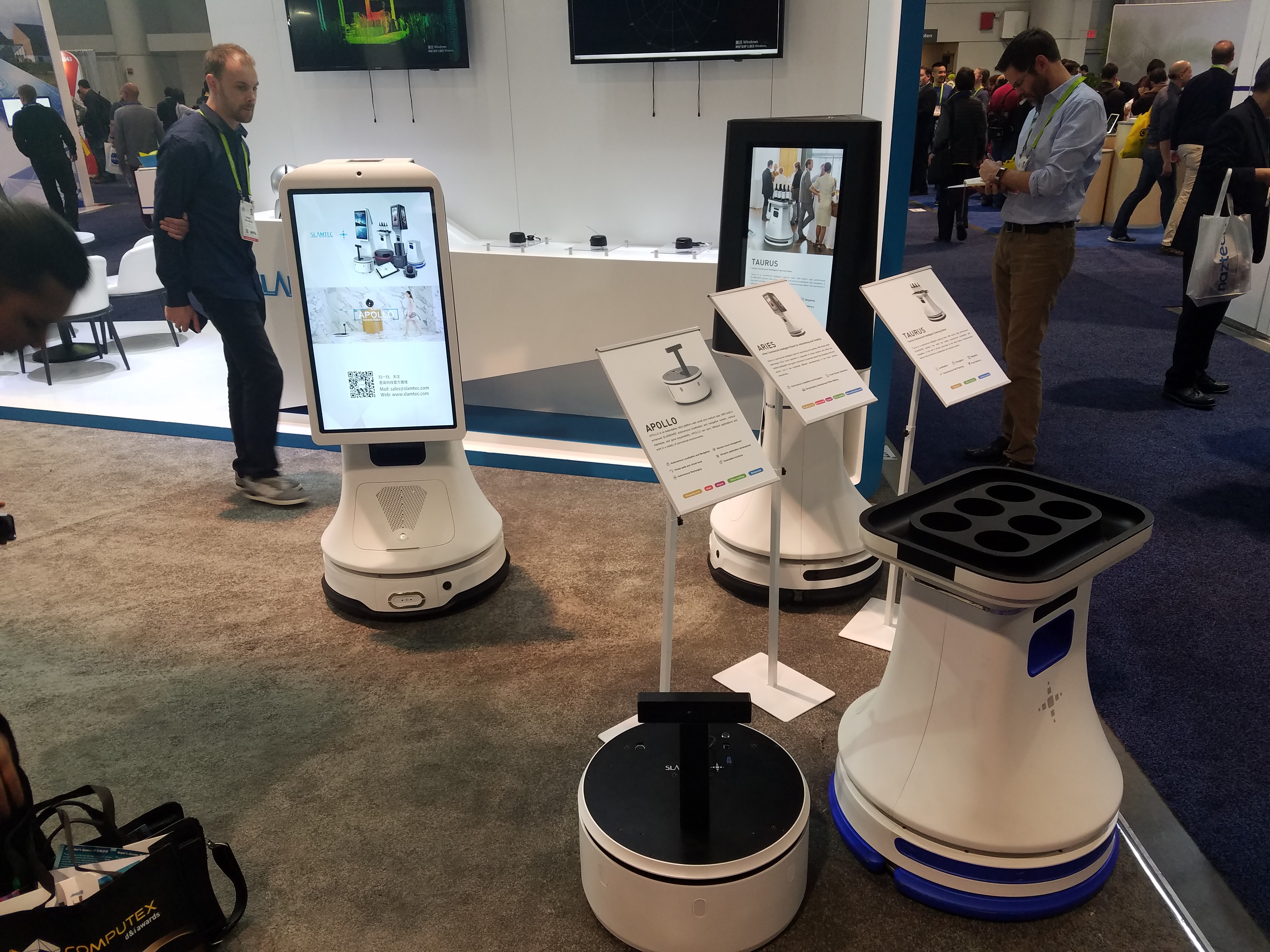
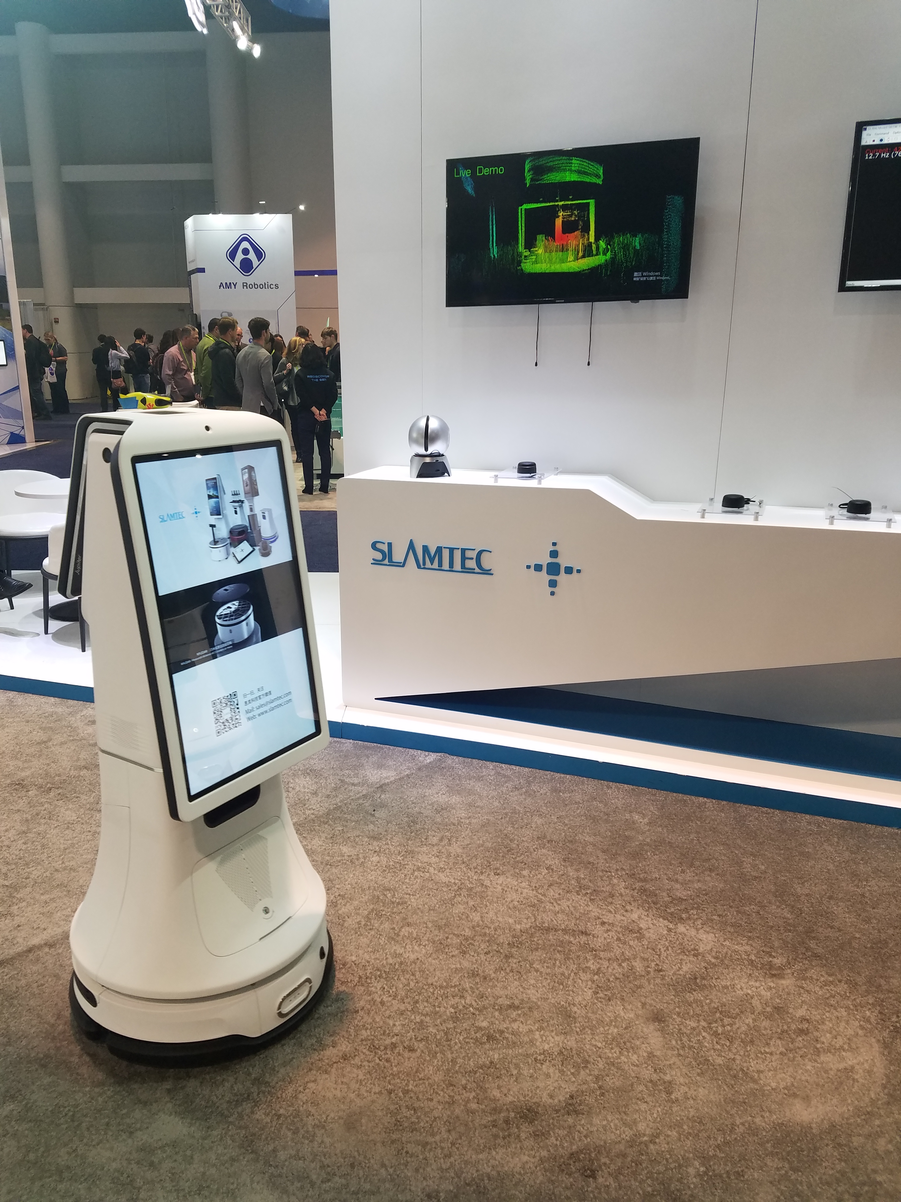
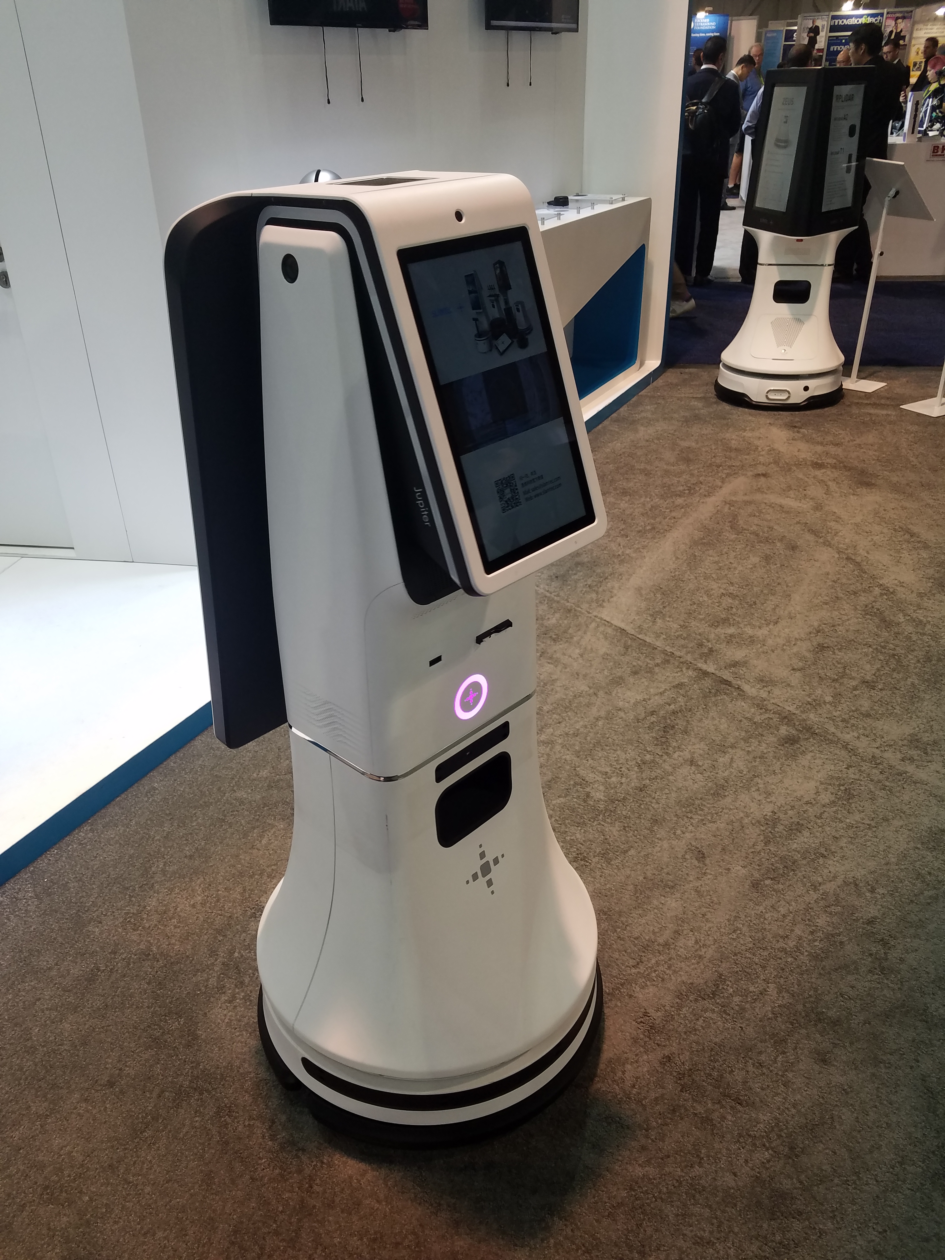
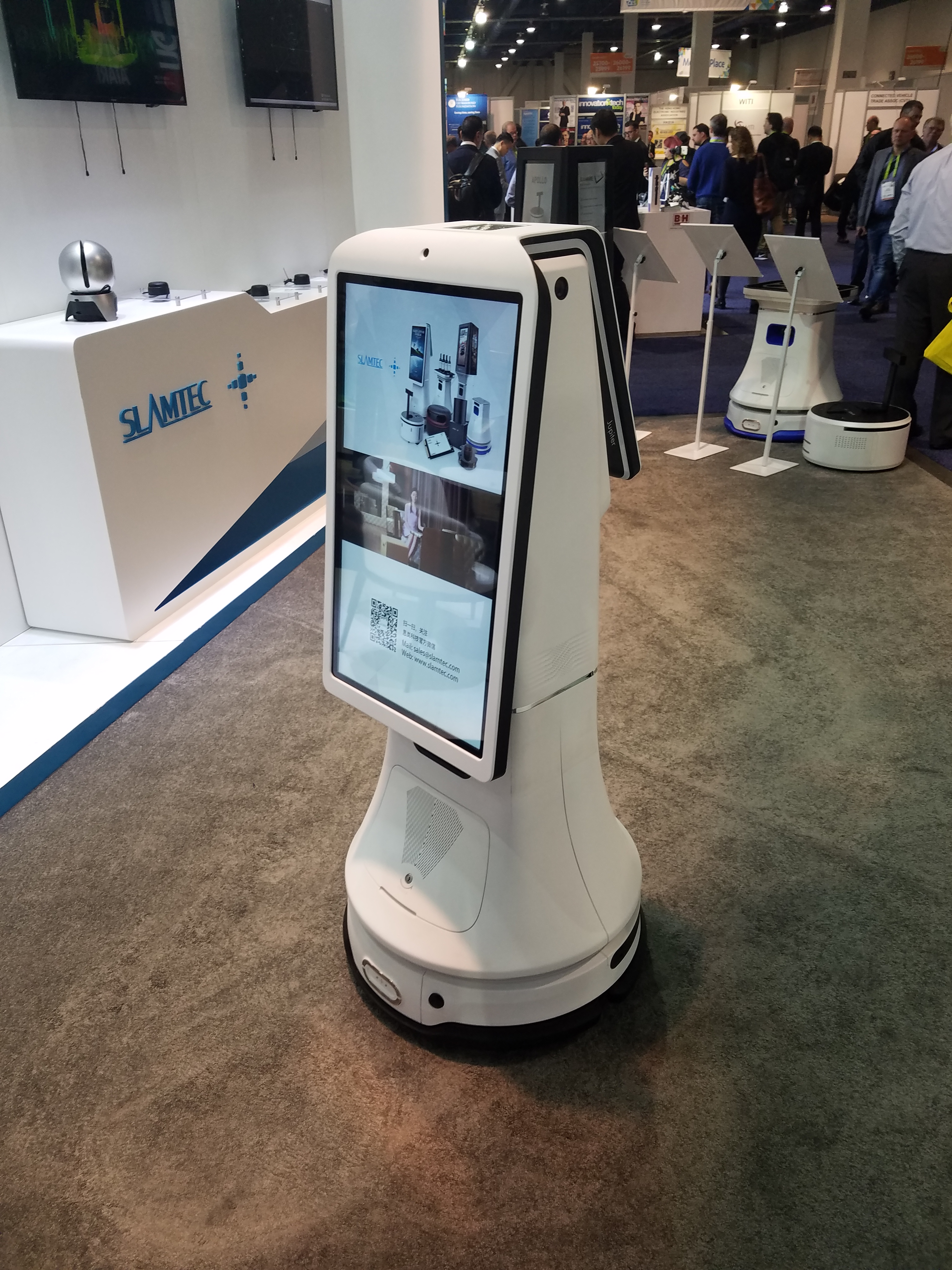
SLAMTEC also has an embedded SLAM solution which they were demonstrating with their Zeus series of mobile robots.
It’s basically a wheeled mobile robot base with capability for autonomous navigation in an indoor environment.
You can then attach an application-specific payload on top, such as a serving tray, kiosk screen or a large advertising screen.
Website: www.slamtec.com/en
|
|
Fig. 35: |
Fig. 36: |
|
Fig. 37: |
|
|
|
Fig. 39: |
Fig. 40: |
Fig. 41: |
|
Fig. 42: |
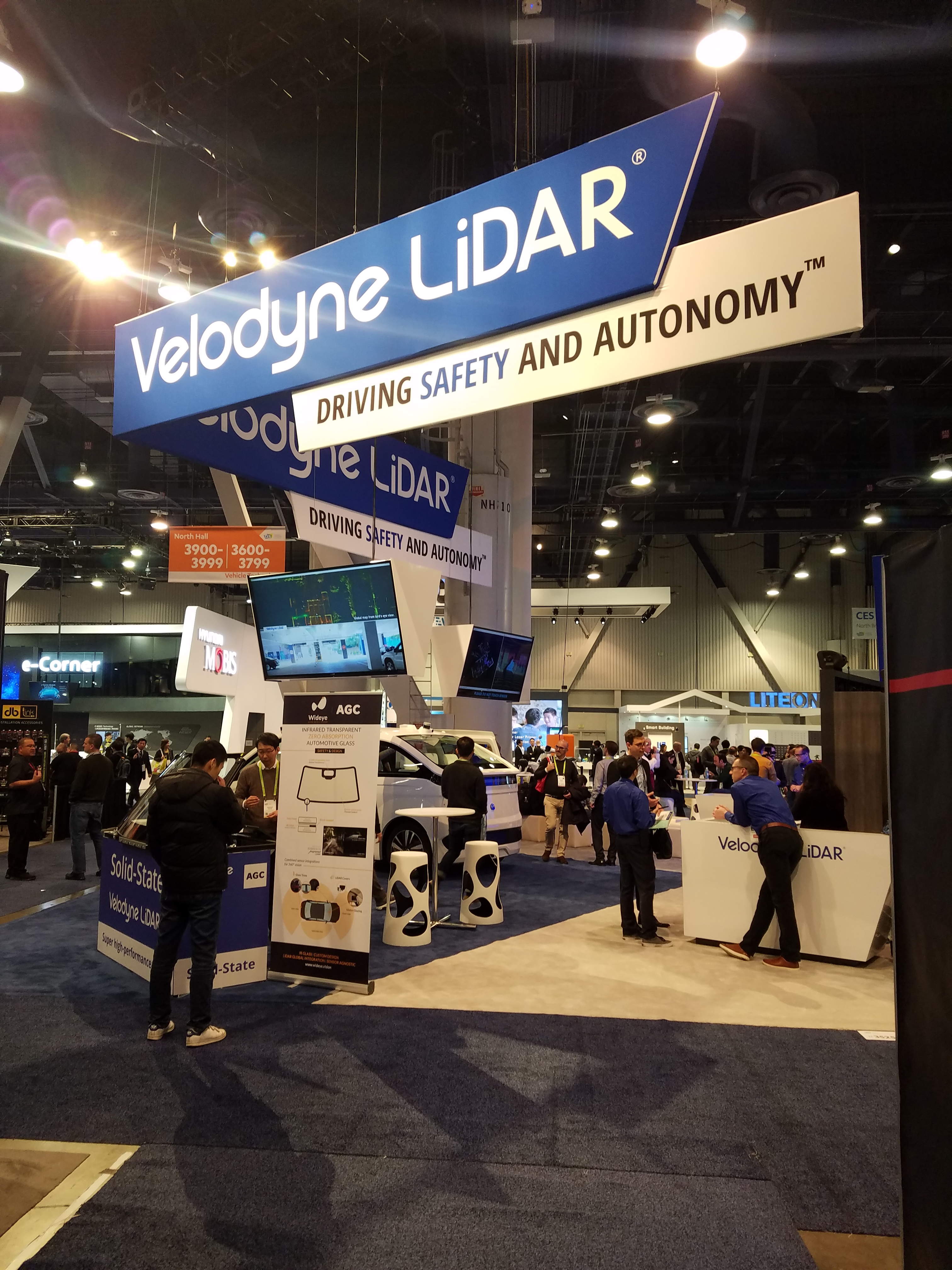
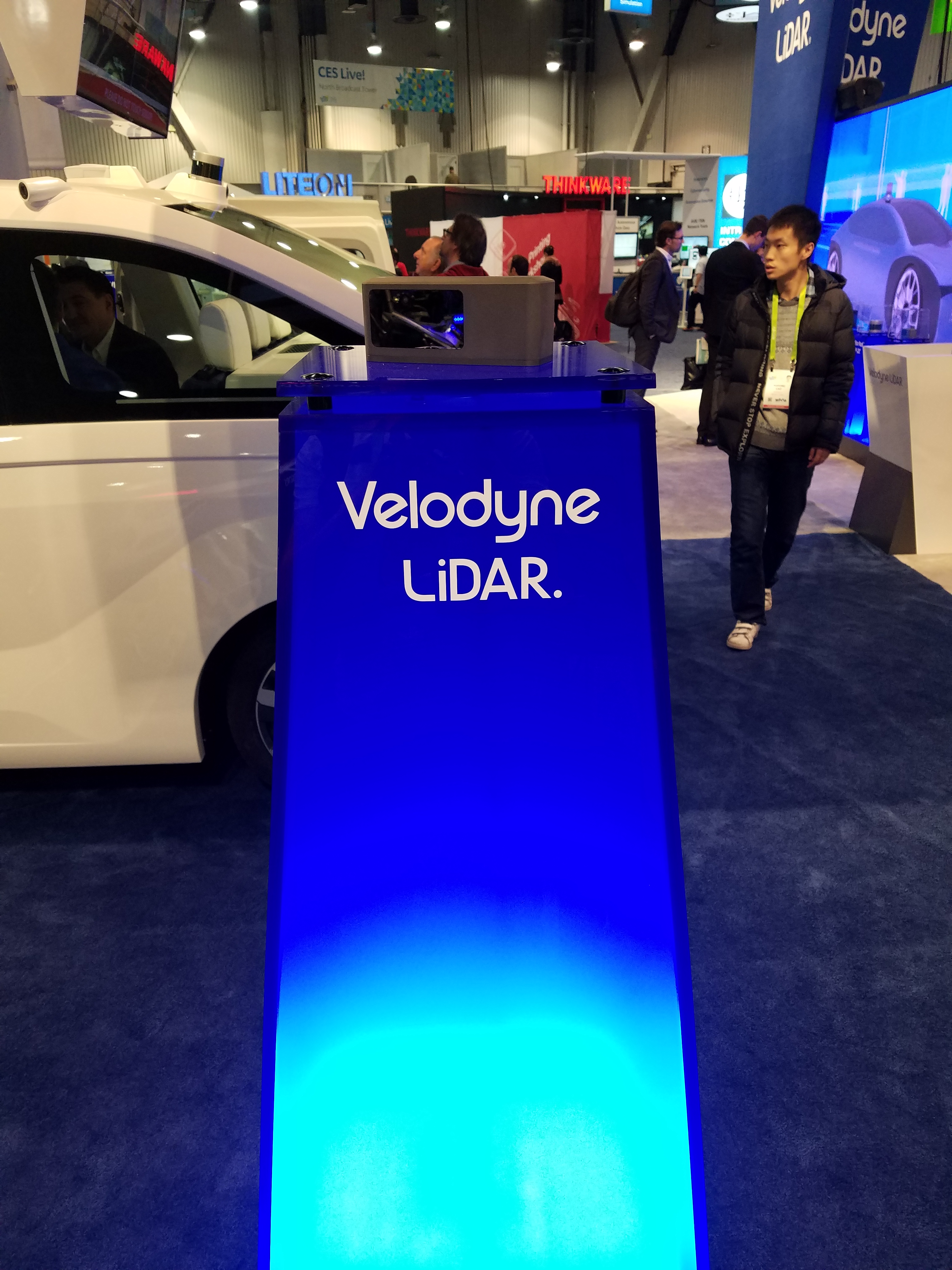
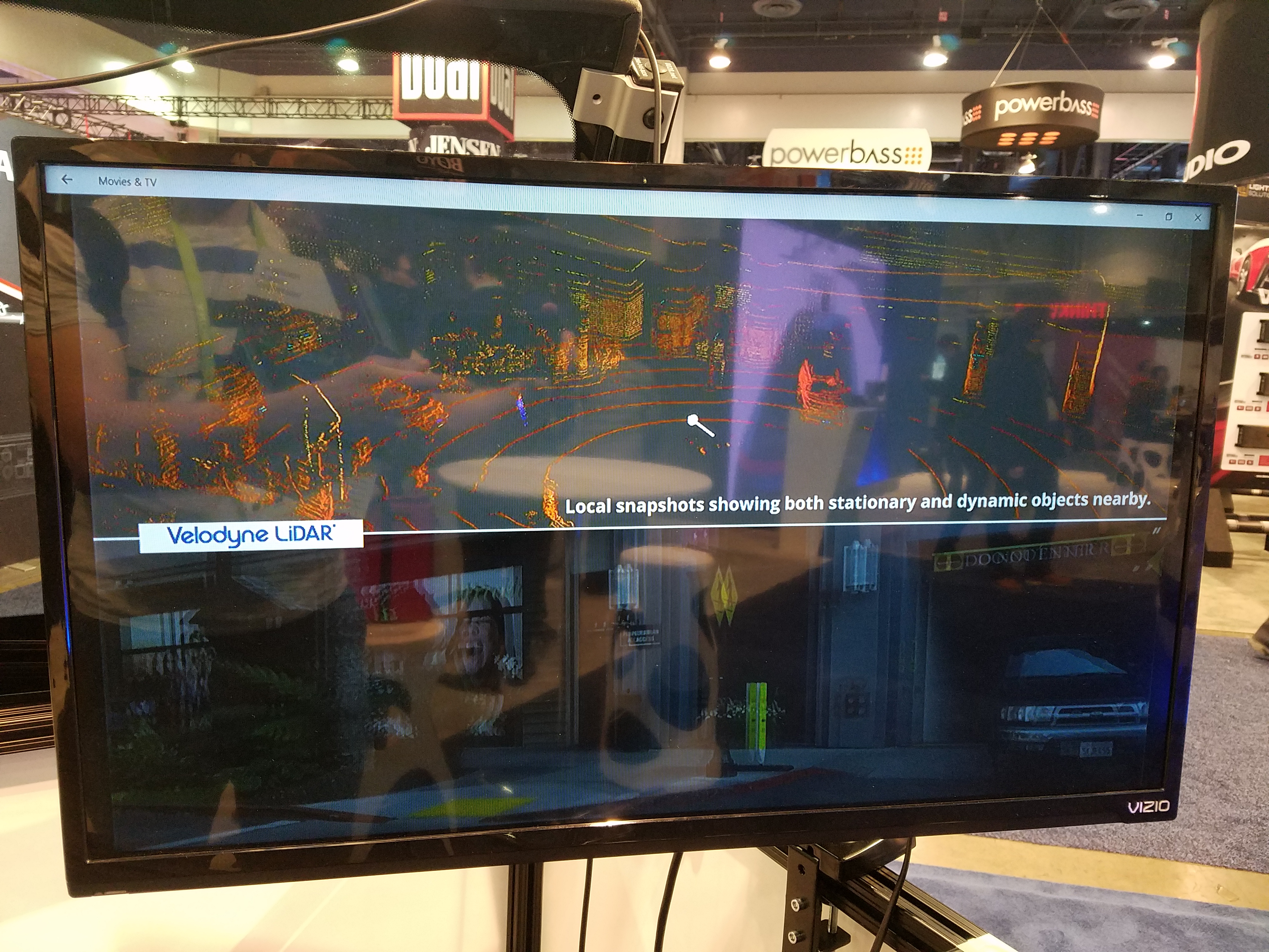
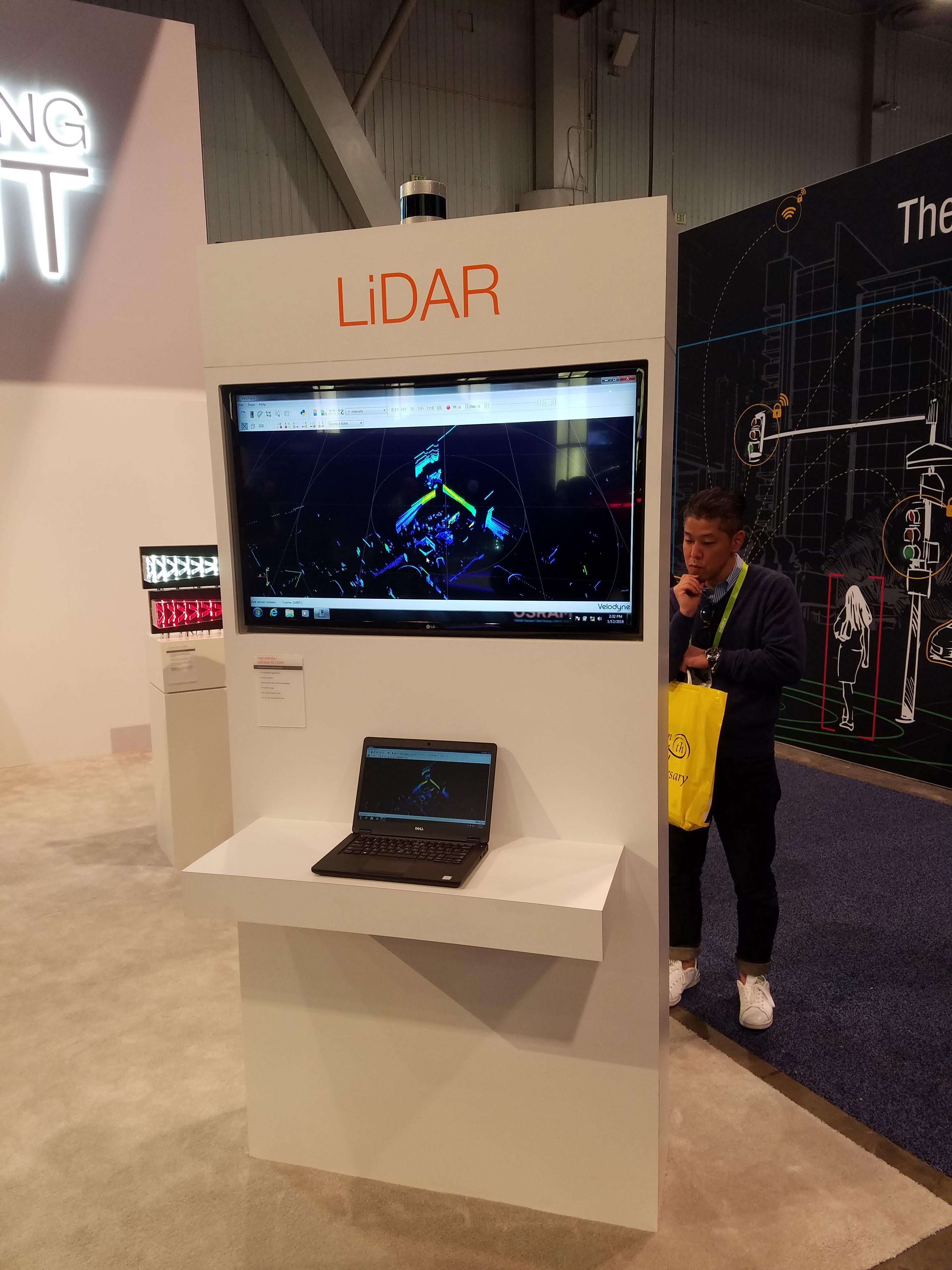
Velodyne
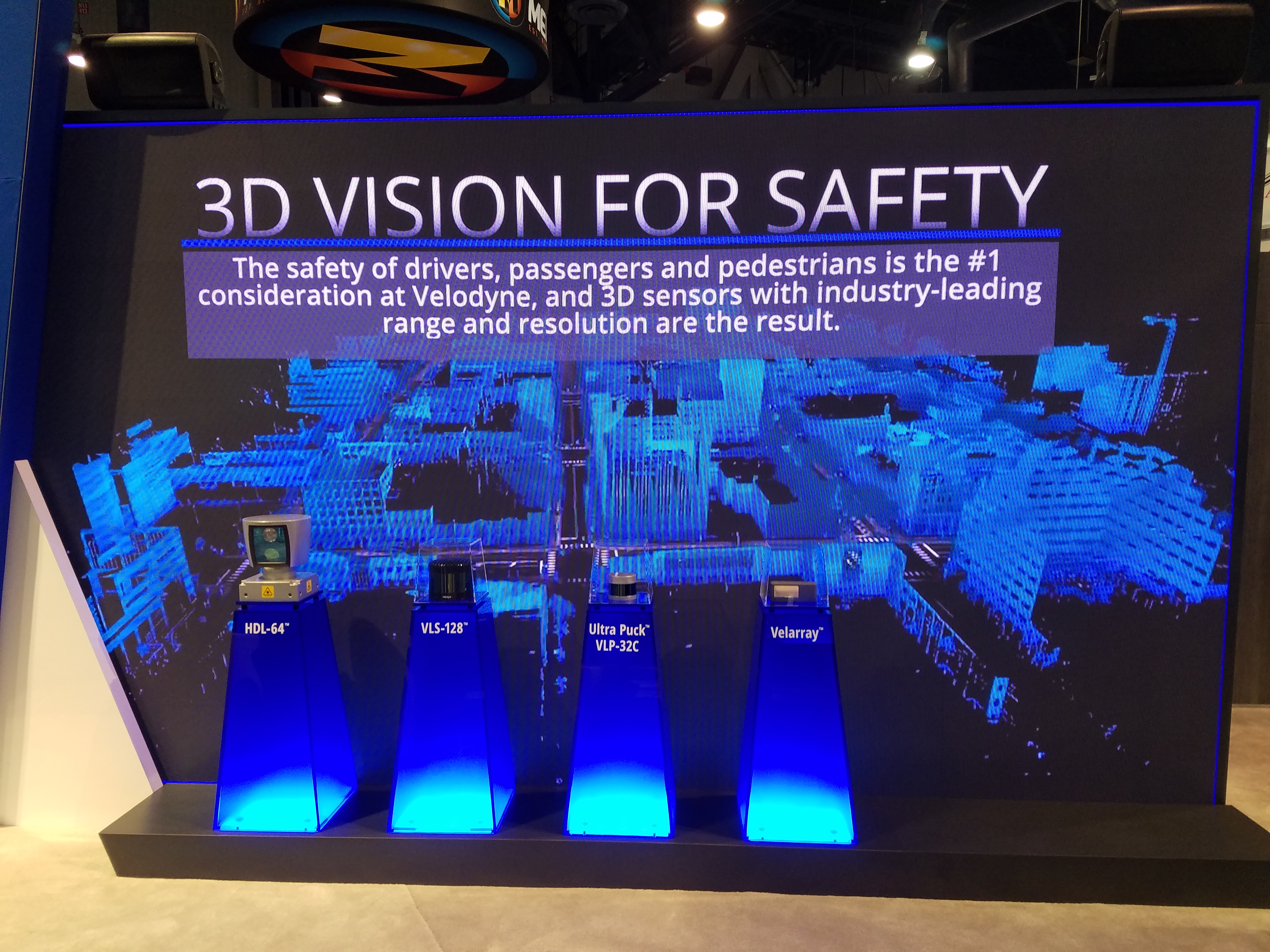
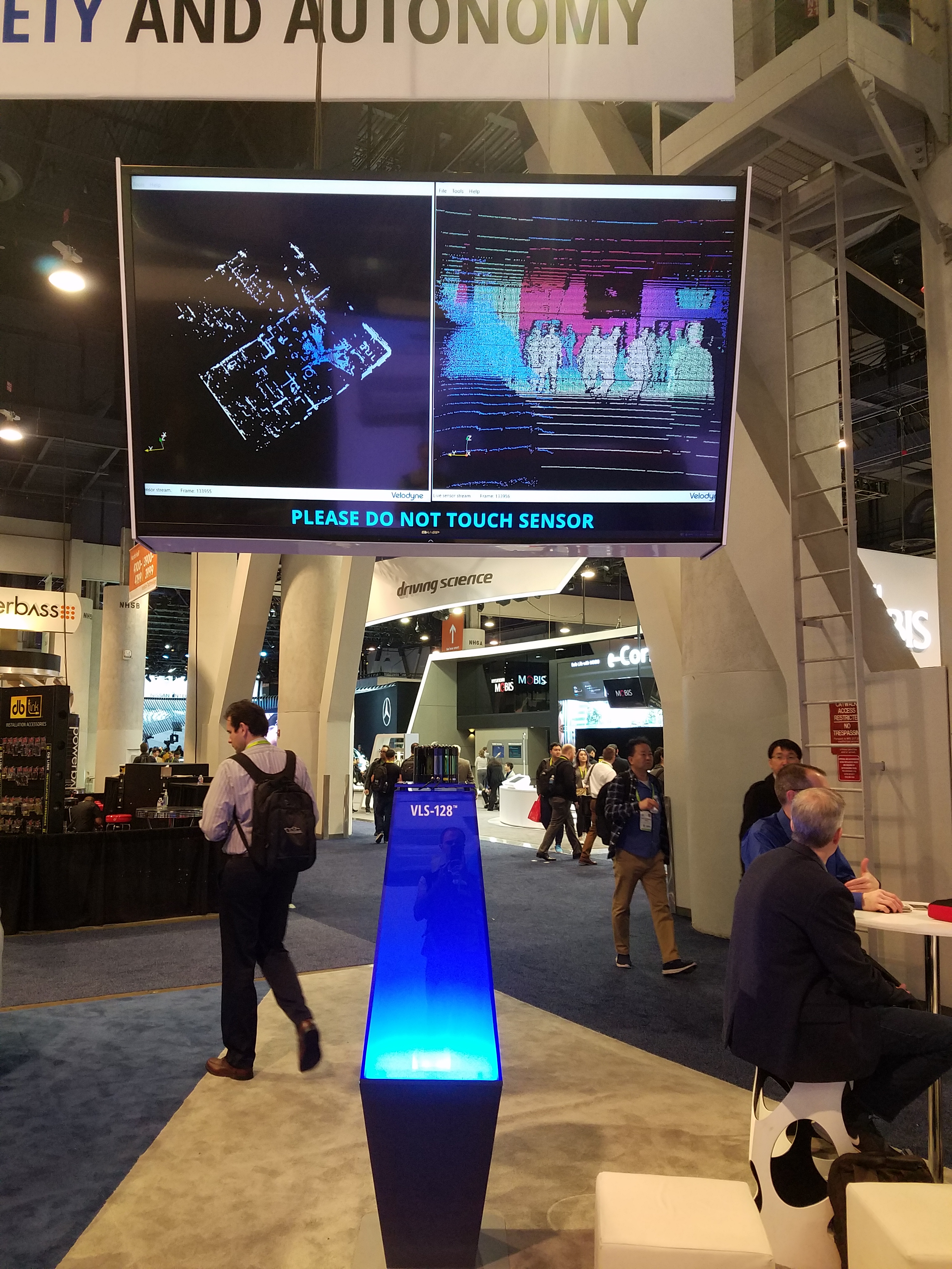
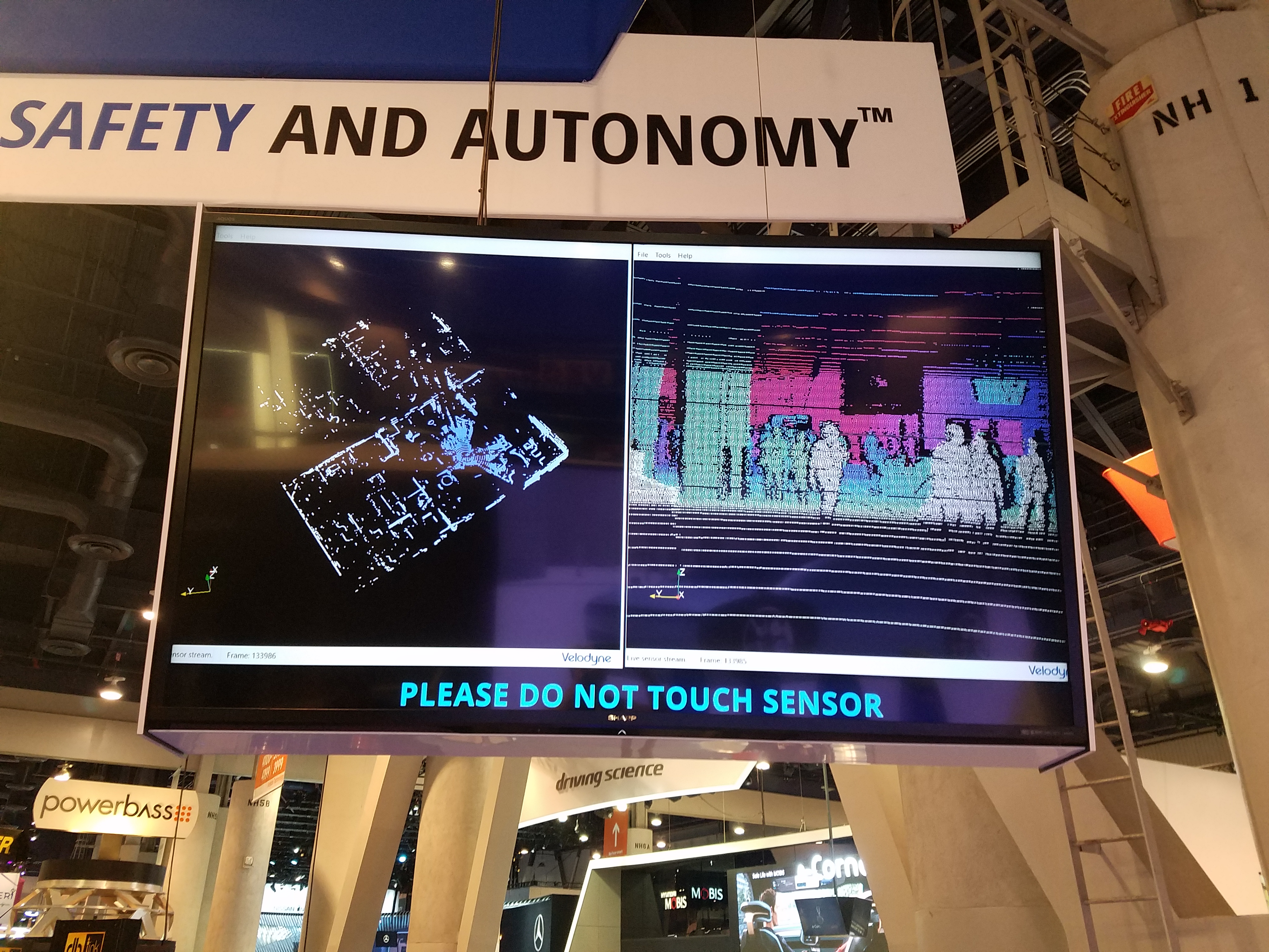
They had live demos of 3 of their LiDAR sensors, which was the most number of working products on display for any LiDAR company.
Their prototype solid-state LiDAR called “Velarray” was on display in a mock-up of a vehicle windshield (windscreen), with a screen showing some pre-recorded output from the sensor. A live demo of the Velarray was available in the back office.
The VLS-128 and VLP-32C sensors were setup such that you could move about and see the result on-screen, demonstrating how much denser the output is compared to previous models.
Website: www.velodynelidar.com
|
Fig. 43: |
Fig. 44: |
|
|
|
Fig. 46: |
Fig. 47: |
|
Fig. 48: |
Fig. 49: |
Fig. 50: |

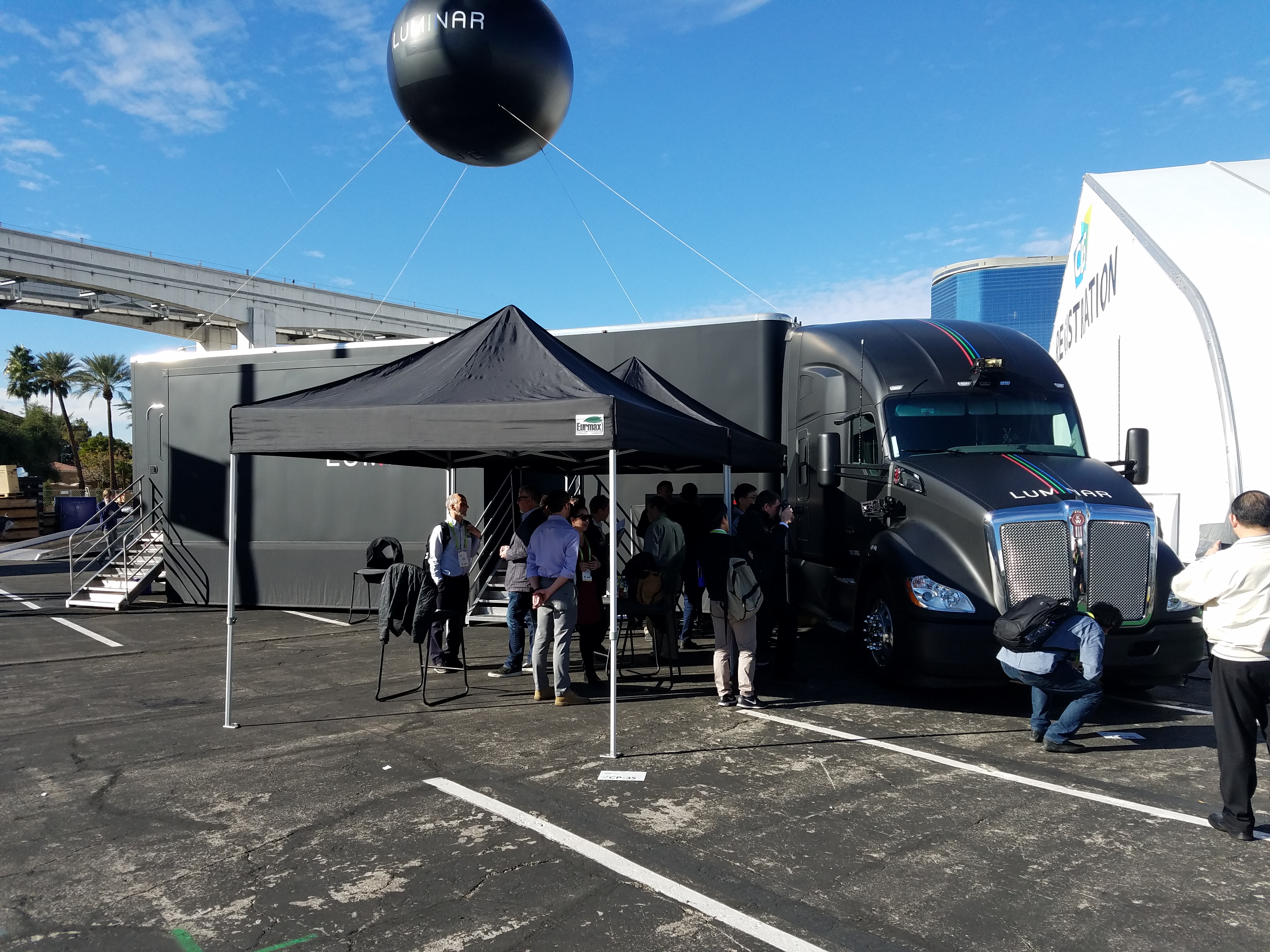
Luminar
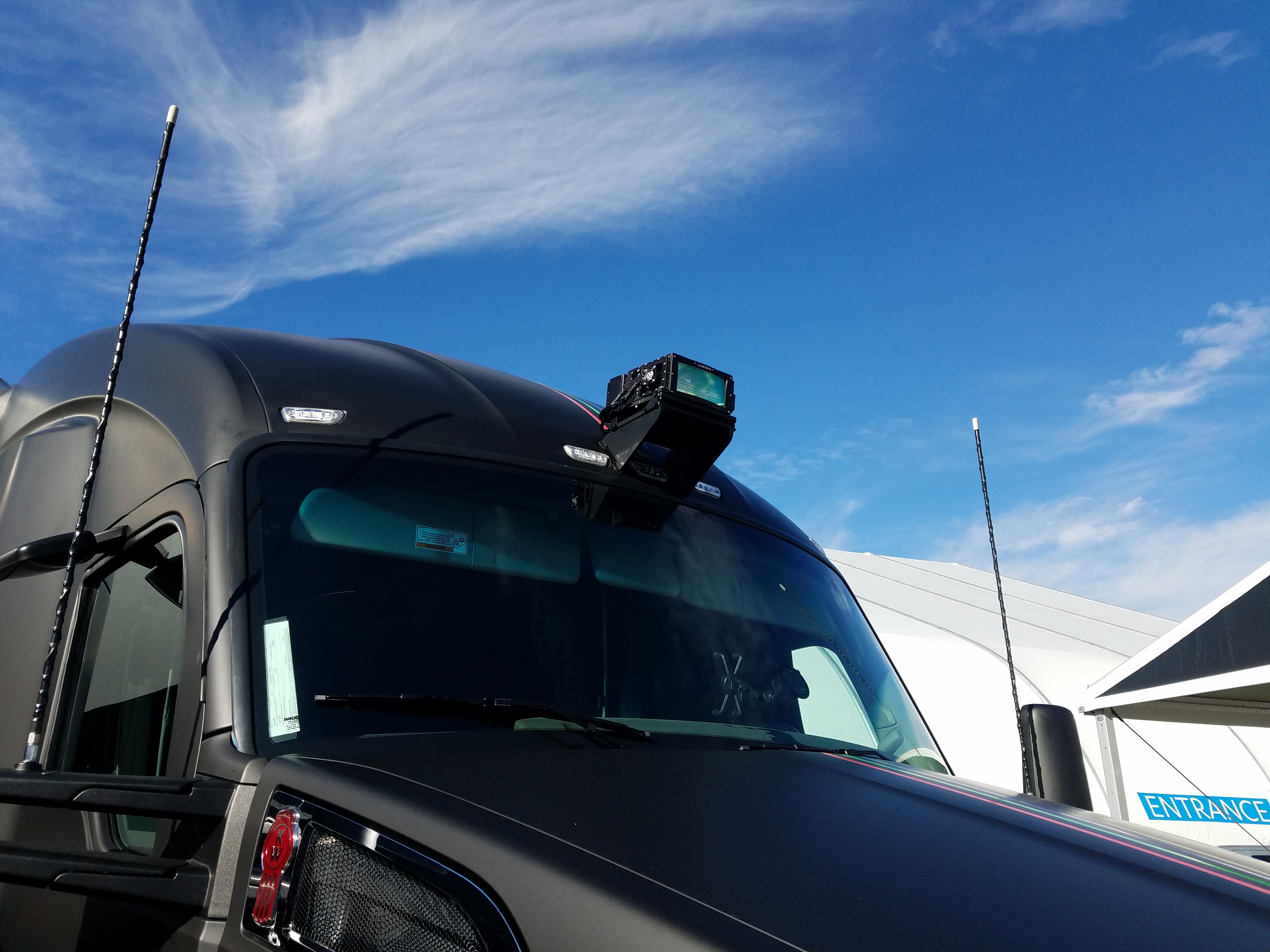
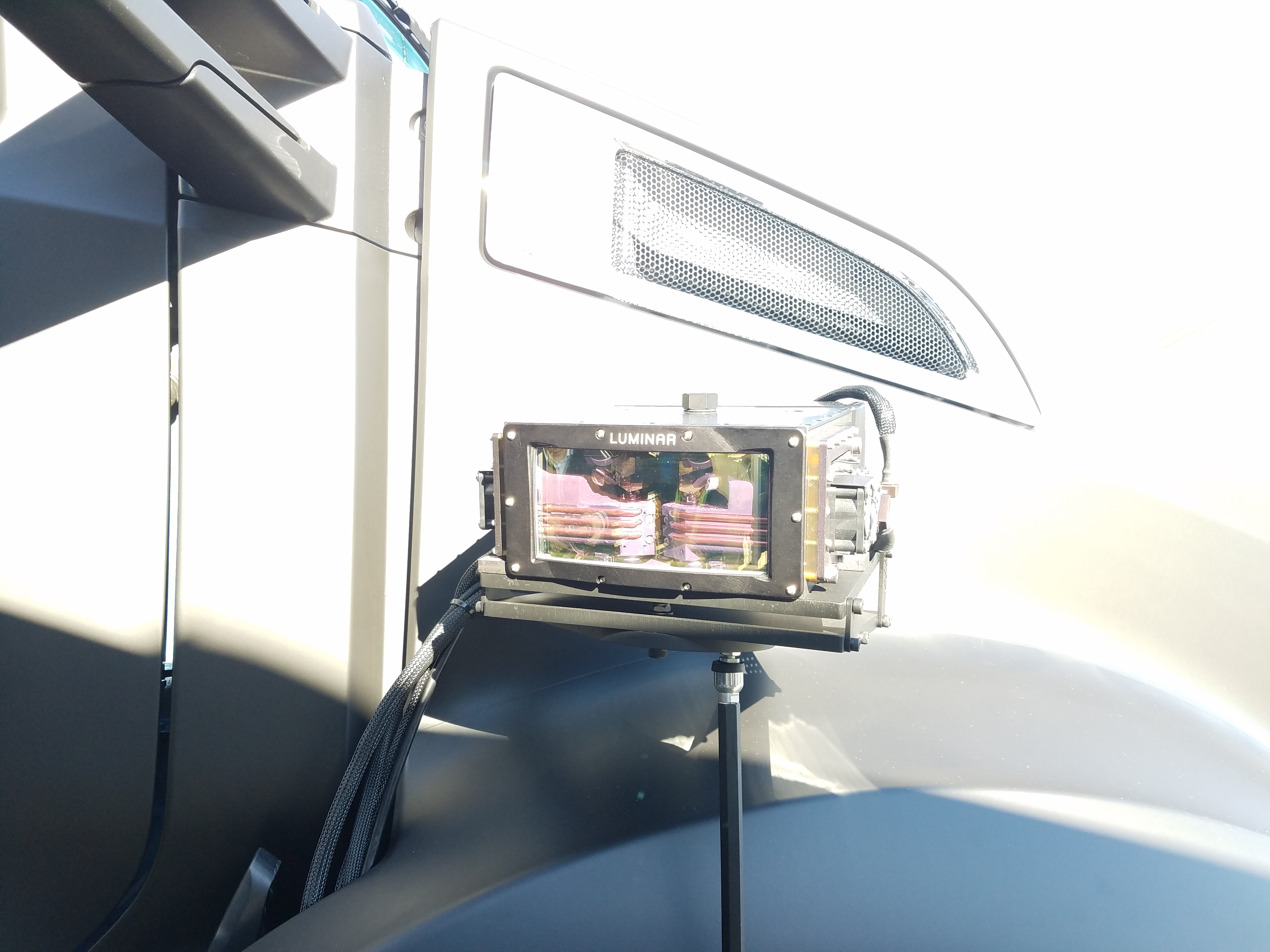
Their booth was a big Kenworth truck and semi-trailer. They had a demo of their new 1550nm LiDAR prototype, with two of them mounted onto the front of the truck (Fig. 51-52).
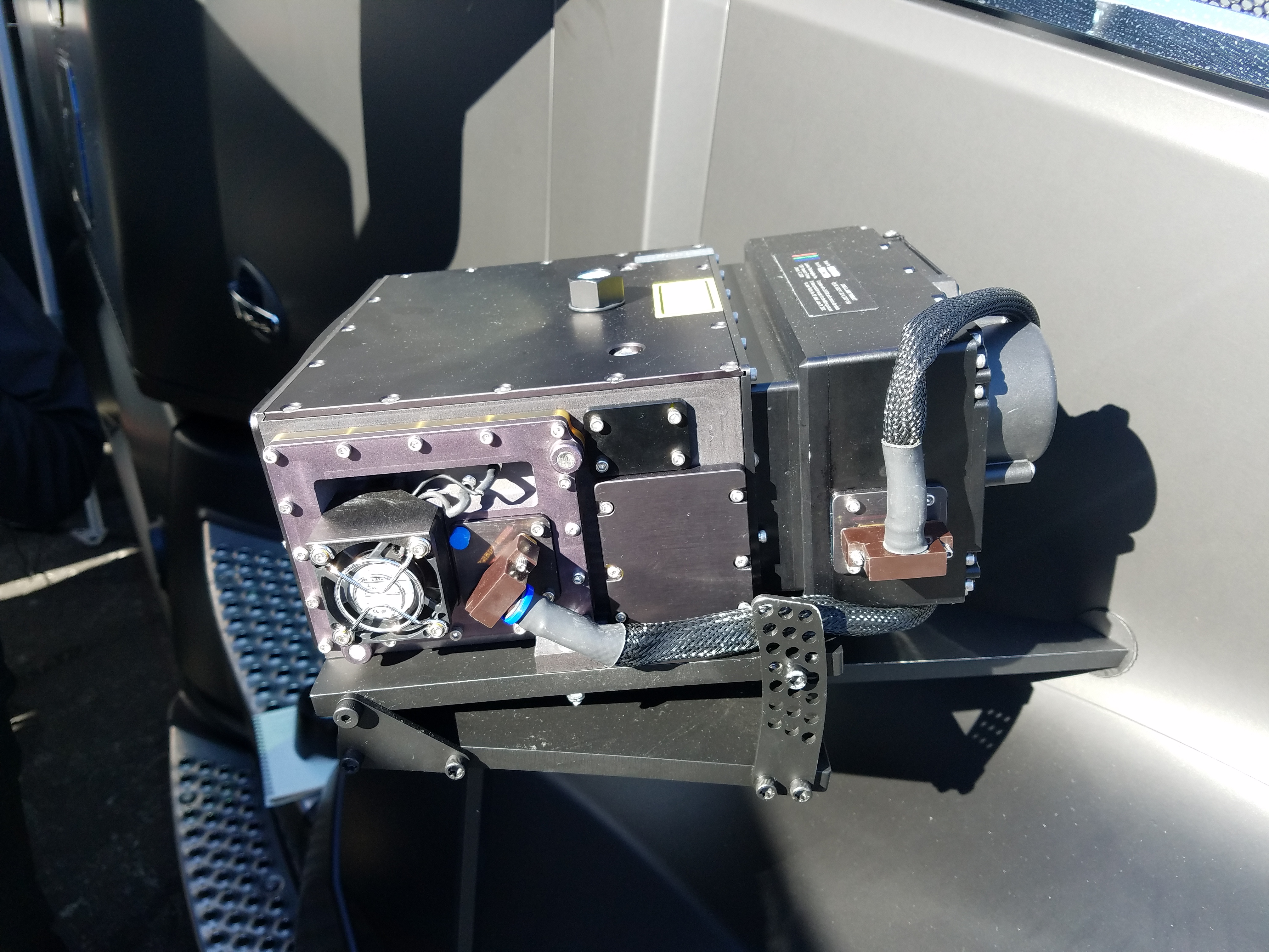
If you look at the design of the LiDAR you can see that it’s actually two LiDARs combined together. By booking in through the front face, you can see two scanning mirrors and each appears to have a heatsink block underneath with 3 copper pipes embedded, for heat disipation (Fig. 53). However, apparently they use only one laser diode which is separated to the two mirrors.
The casing has a rugged design that looks like a piece of futuristic mil-spec hardware (Fig. 54). There are identical cable connectors on the side faces, for connectivity to the two lasers. I like how the casing is fabricated with interlocking metal plates and dovetail joints, for ease of manufacturing.
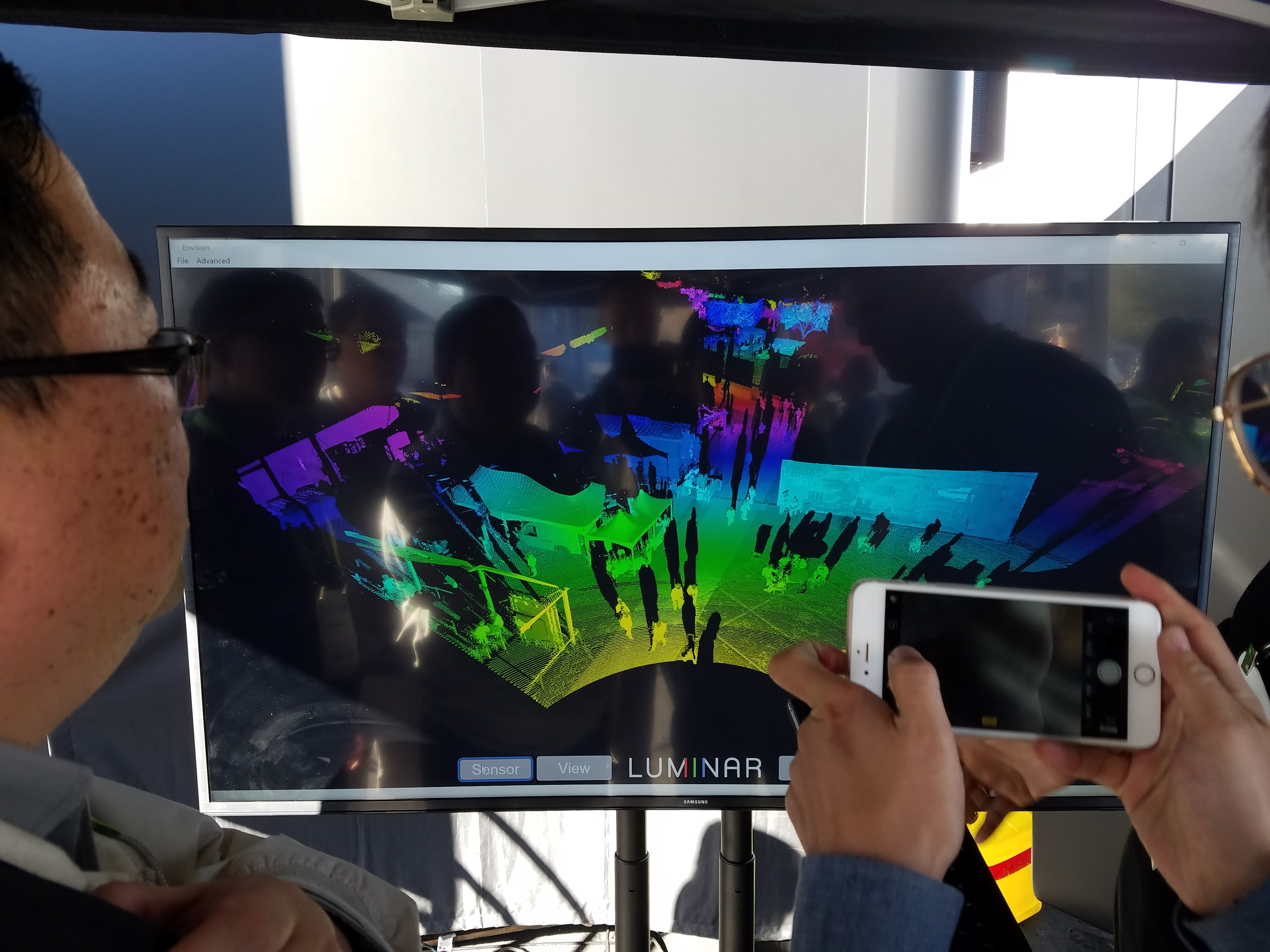
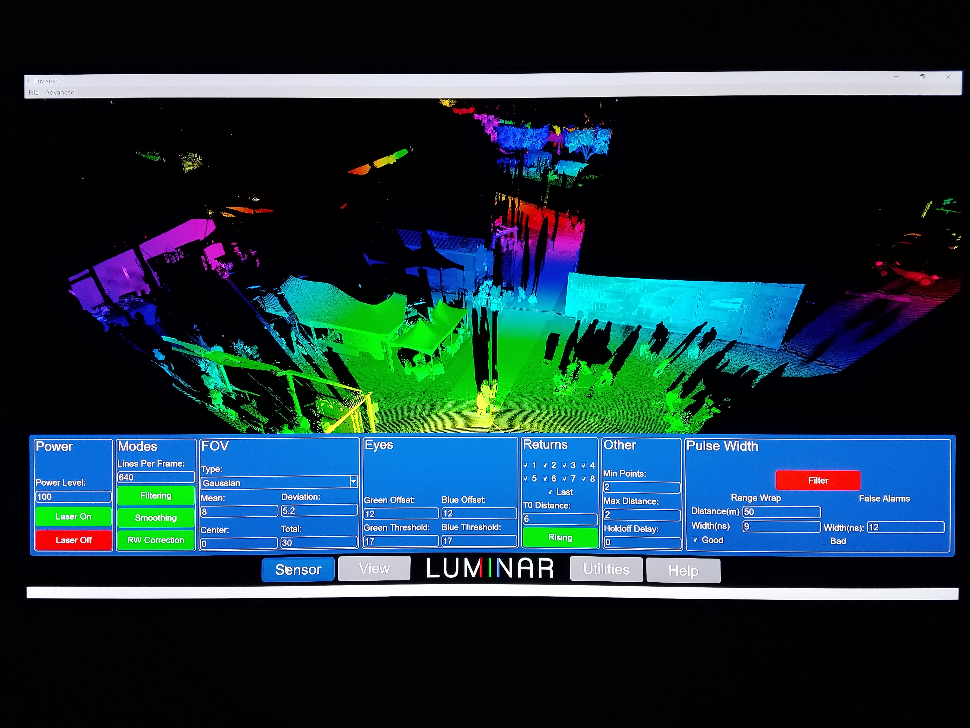
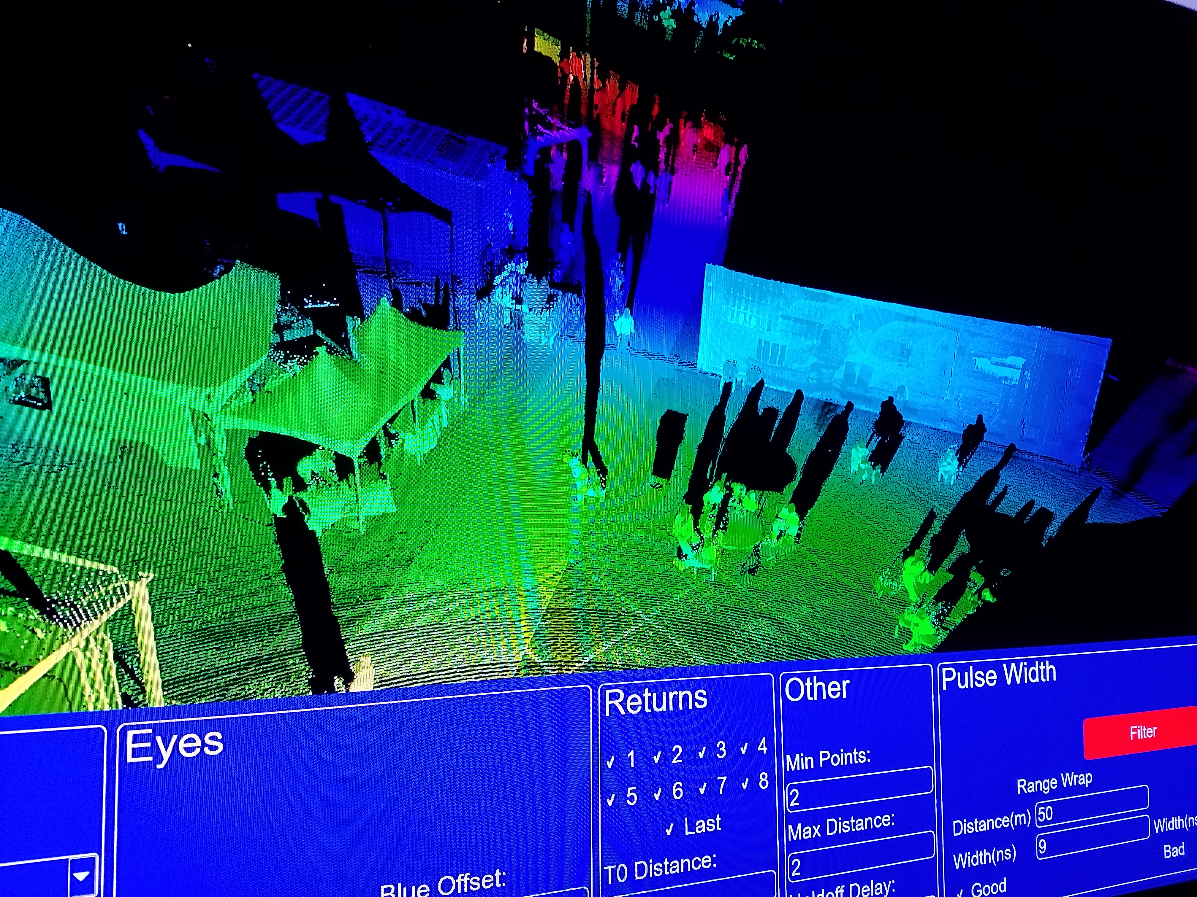
The LiDAR was capturing the nearby environment, which was displayed on a big screen (Fig. 55). From the point cloud you can see the scanning pattern made by the two lasers, with each pattern overlapping in the middle of the field of view (Fig. 57). One interesting thing is that when a person walked across the field of view, there was a distortion or mis-alignment as they moved through the area of overlap, like a discontinuity in the depth (distance) measurement between the two lasers.
They also had a demo video playing inside the truck trailer (Video 8). It shows the sensor output whilst driving on the highway and the Las Vegas strip.
Website: www.luminartech.com
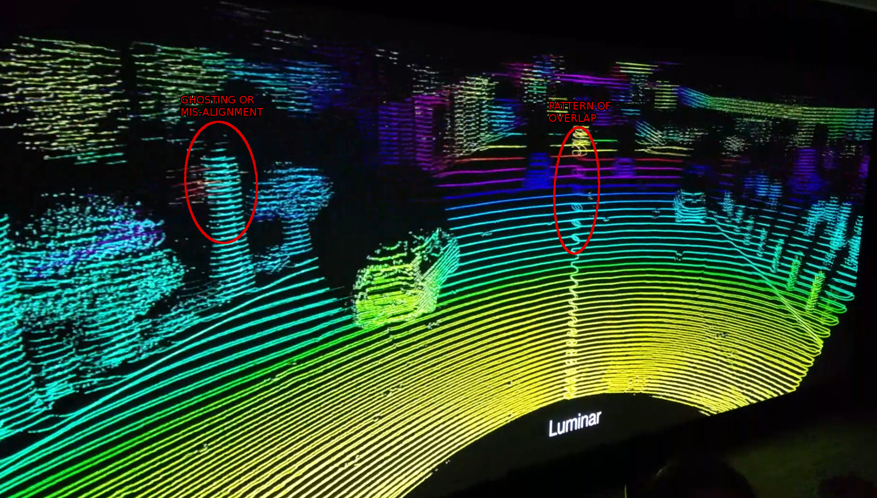
If you look closely at the demo video, you might notice some unusual artifacts in the 3D point cloud. I’ve circled two in Fig. 58:
– Ghost objects (double vision), where two frames of a tree or pedestrian are misaligned.
– The overlap of the scanning pattern in the center seems to diverge as distance increases.
In some of Luminar’s media photos you can see that the LiDAR sensor is plugged into a large control box (Fig. 59). This could be for post-processing or logging the data. It could also be a power supply for the lasers, which suggests that the laser is very power-hungry. It would mean that the main unit is just a remote laser “head” and further miniaturization would be required for the final product. Also, if you’ve seen that Toyota has put 4 Luminar LiDARs on their latest AV then I wonder if they had to fit 4 of those control boxes inside the vehicle?
|
Fig. 51: |
||
|
Fig. 52: |
Fig. 53: |
Fig. 54: |
|
|
|
Fig. 57: |
|
Video 8: |
|
Fig. 59:
Testing the LiDAR sensor. Notice the large control box on the bench. 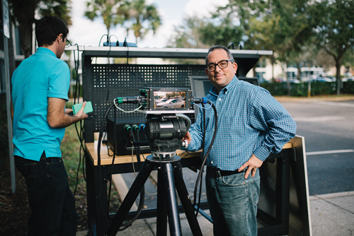 Luminar |

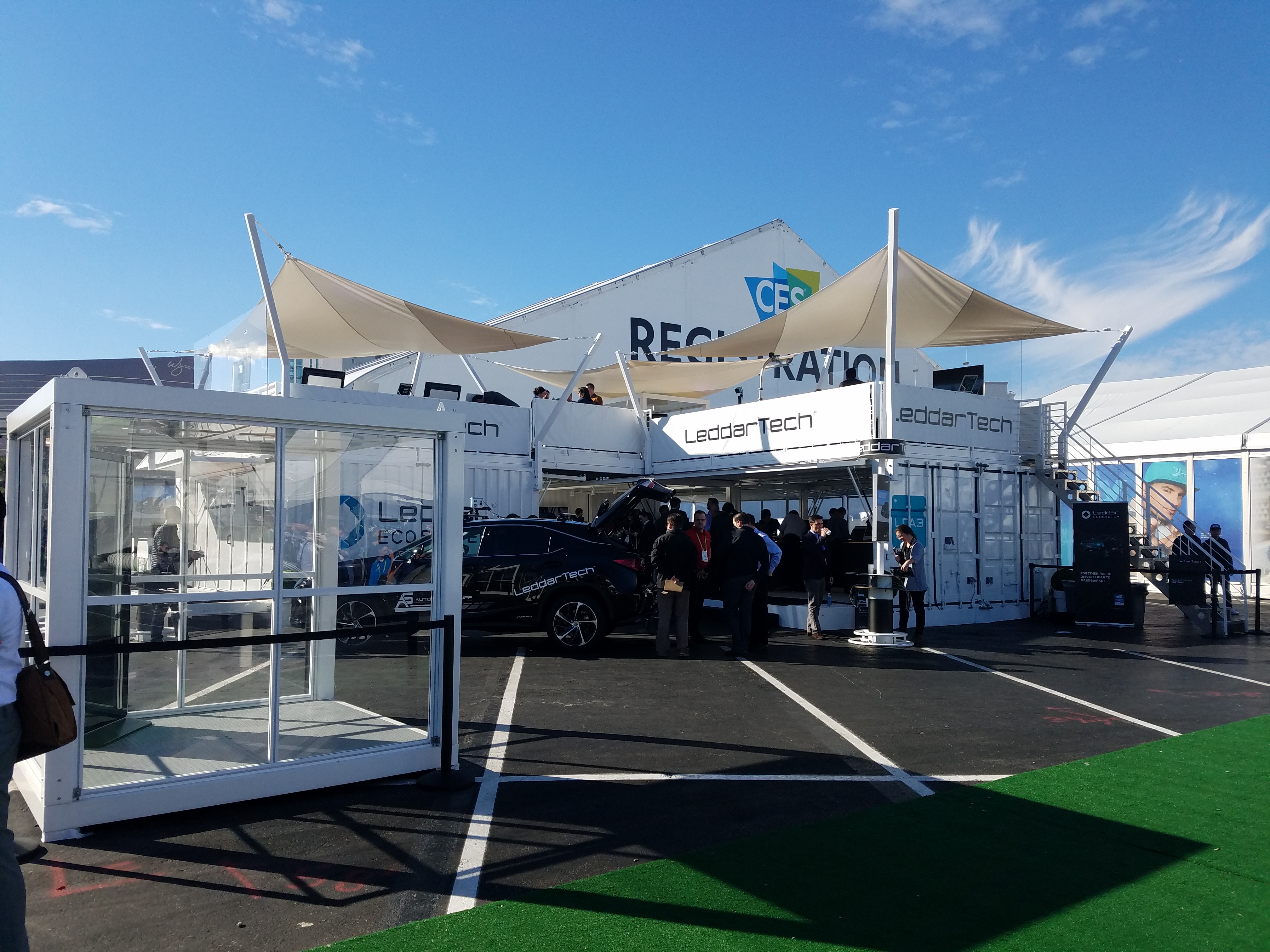
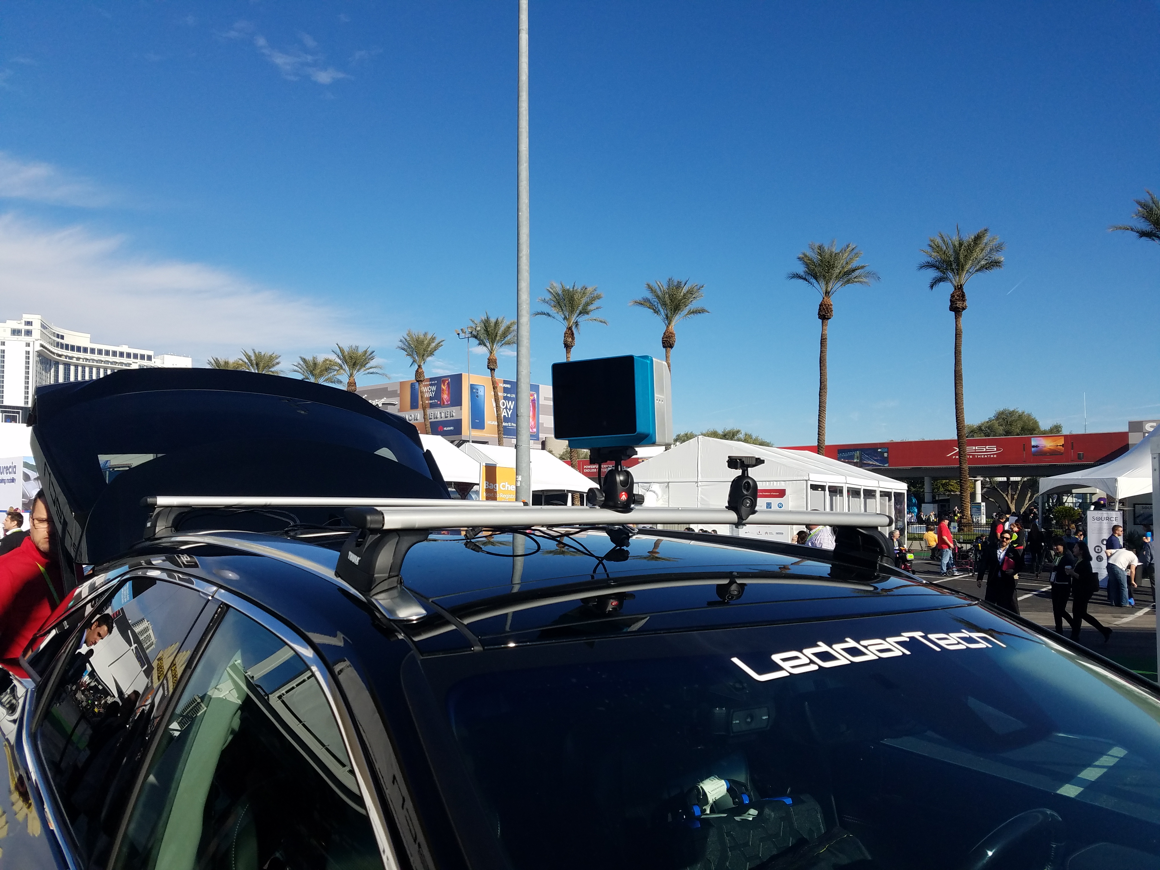
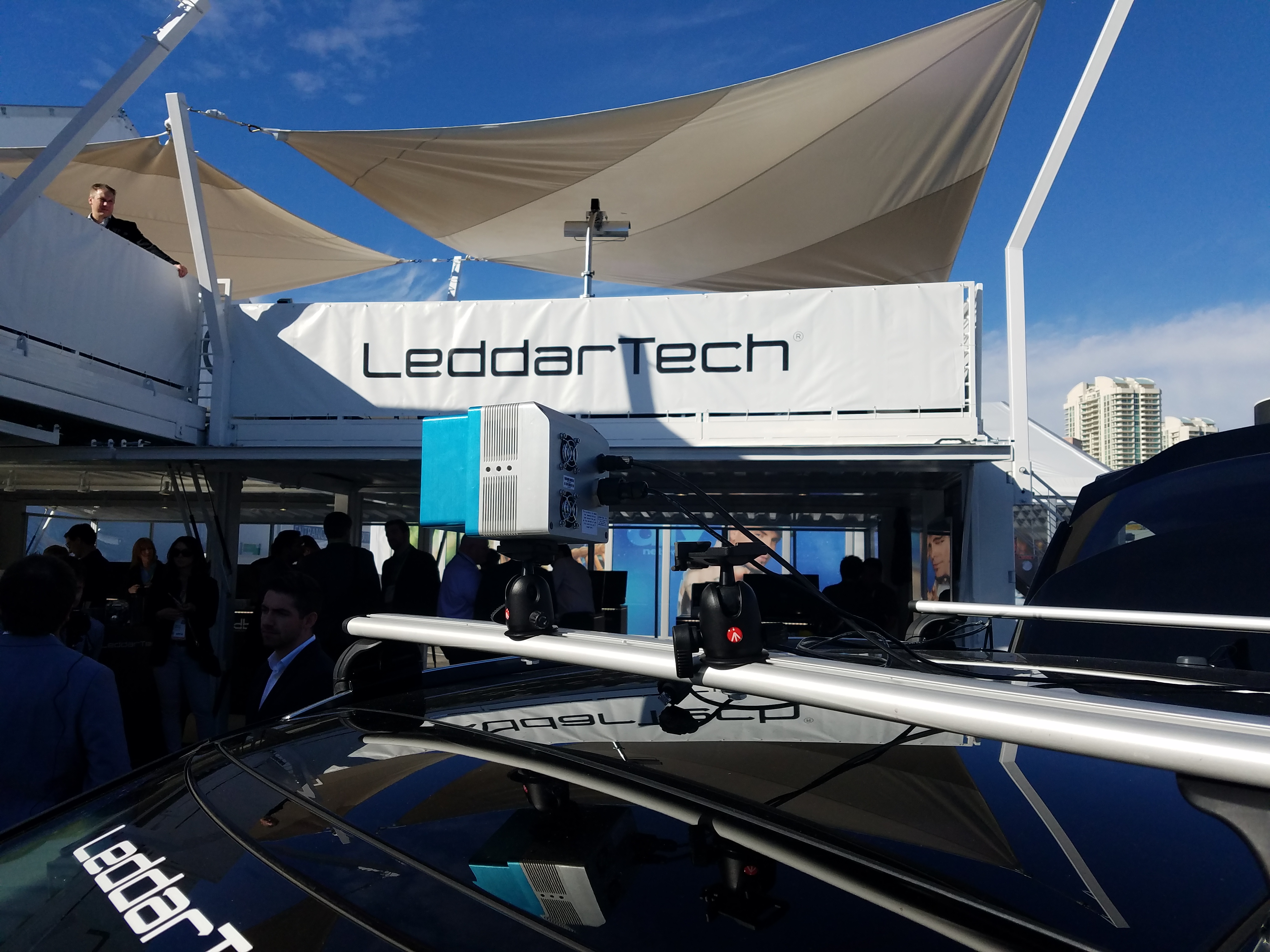
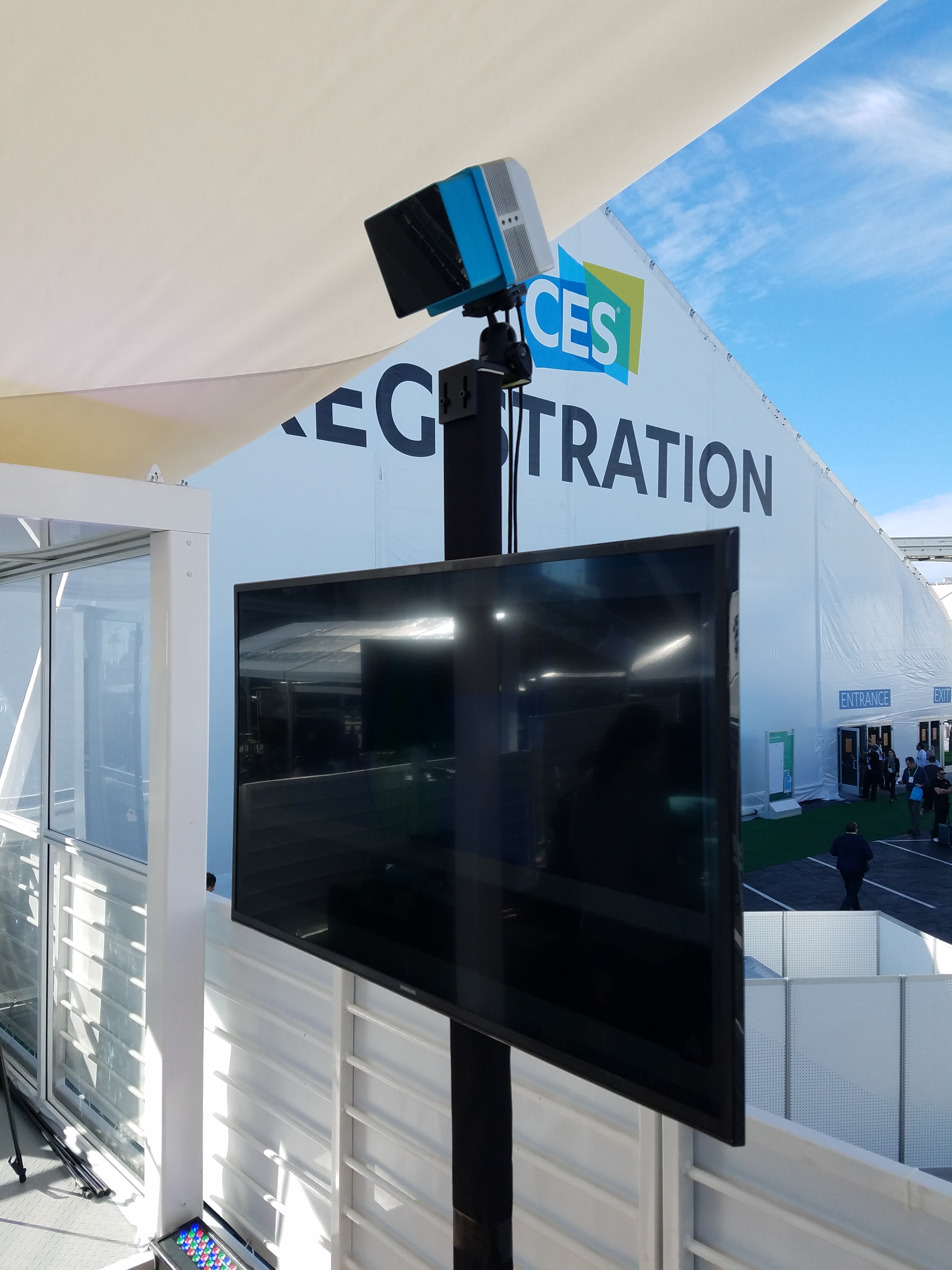
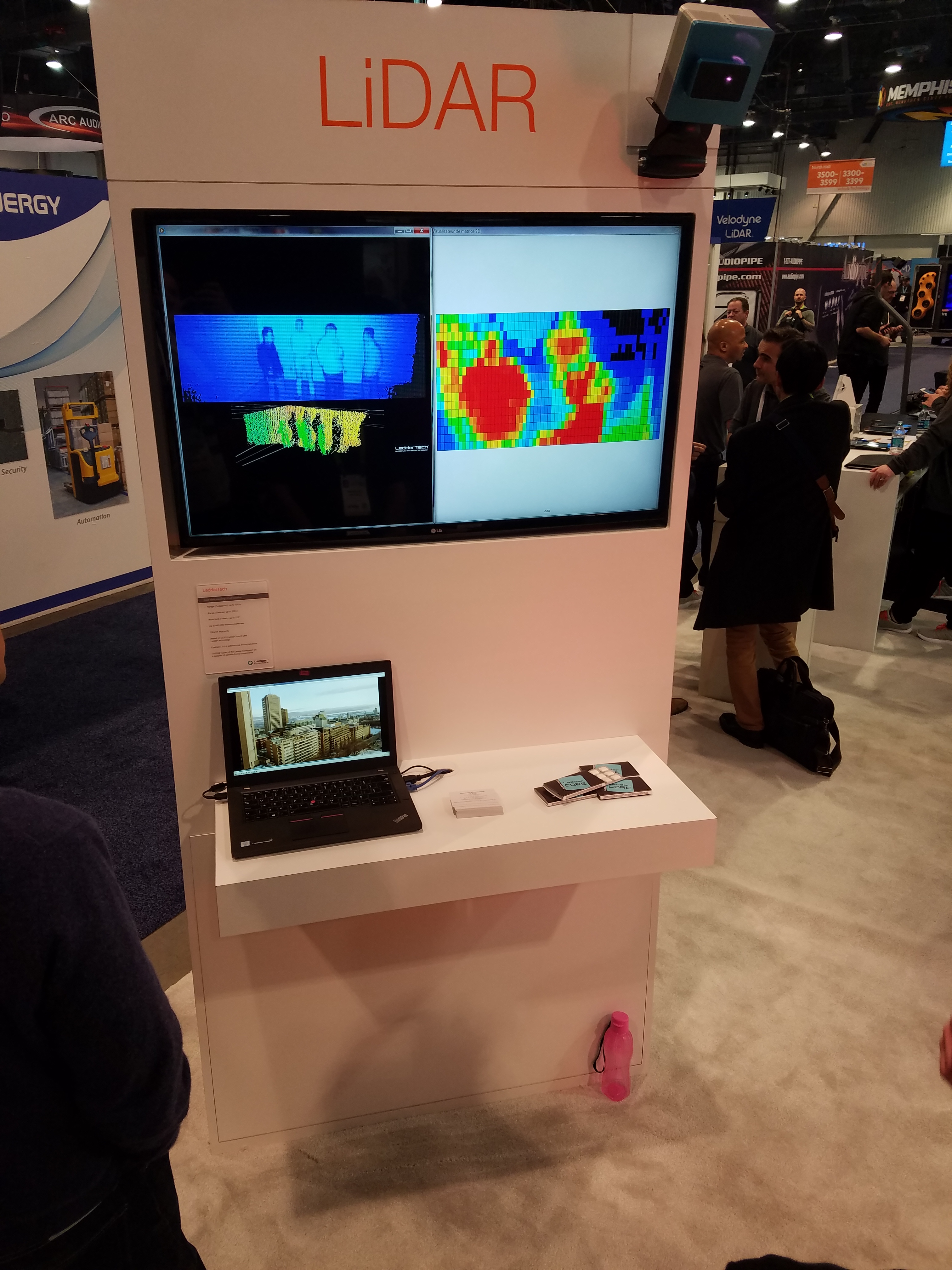
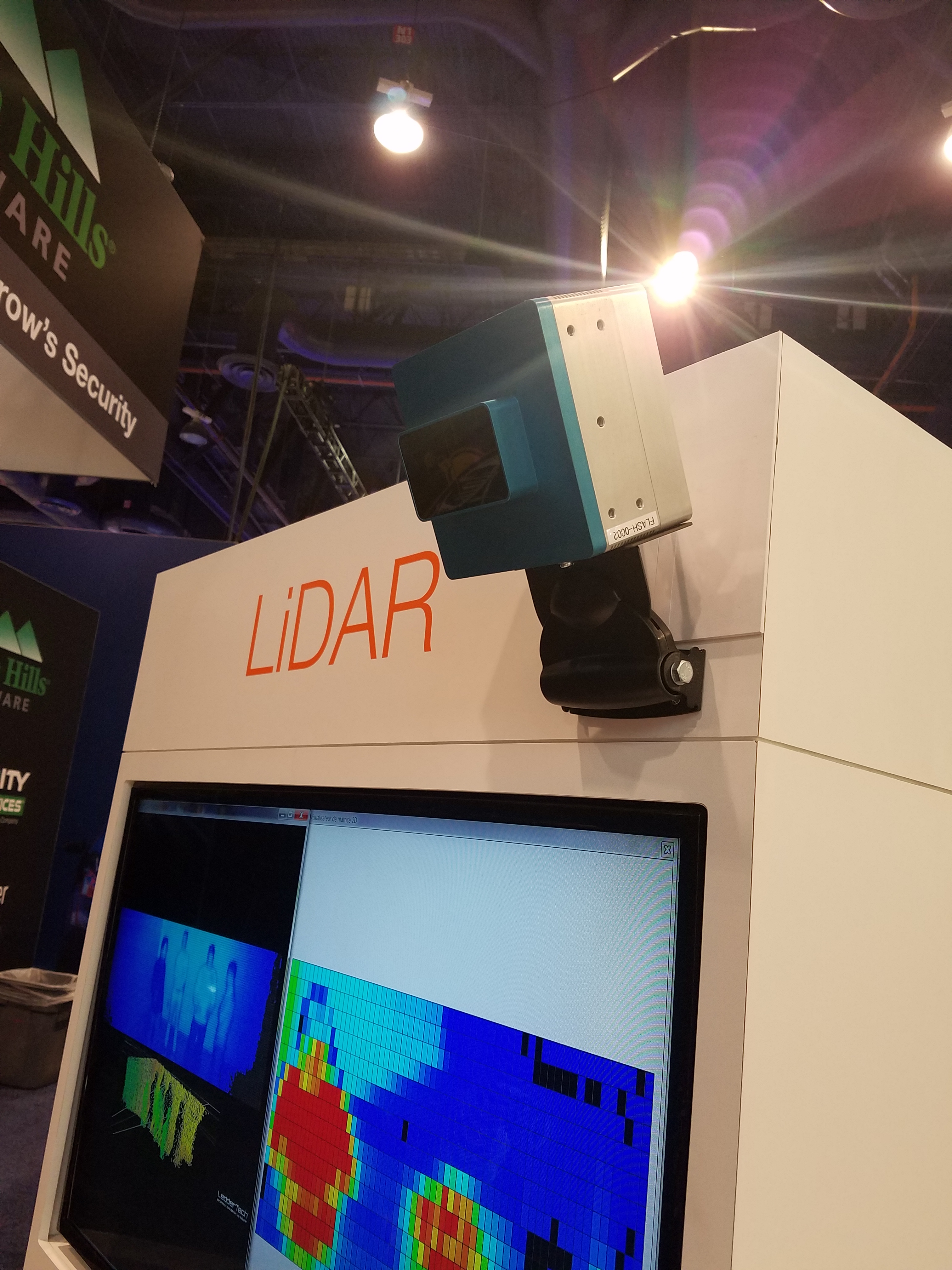
LeddarTech
They were promoting their SOC (System on Chip) for solid-state LiDAR devices called “LCA”.
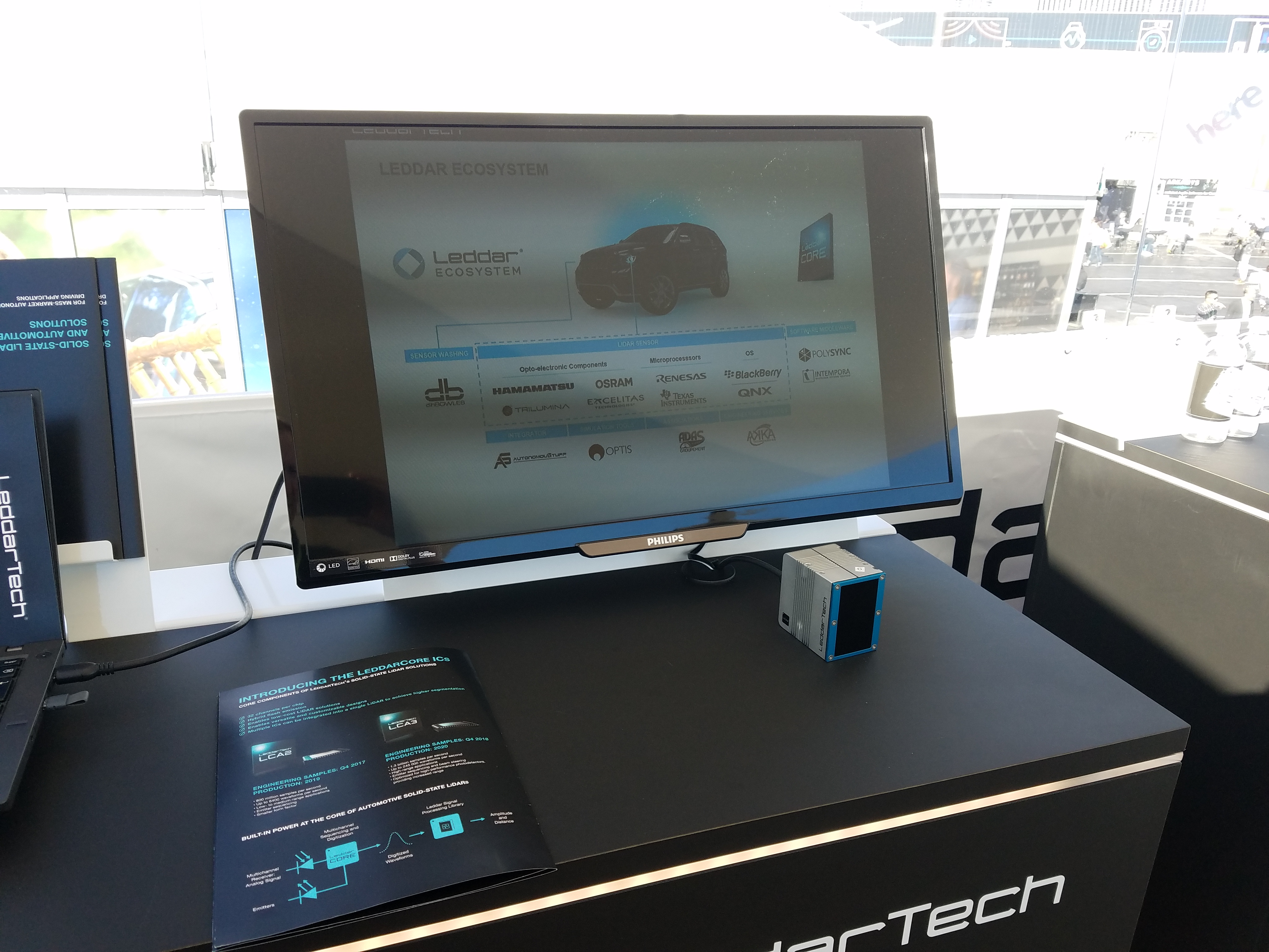
In Fig. 61 you can see two of their multi-channel LiDAR products and another “Flash LiDAR” that uses their LCA2 chip.
What was most interesting is that they had various prototype LiDAR sensors on display that are different to the products pictured in their marketing materials. They had a prototype “hybrid Flash LiDAR” mounted to the roof of a vehicle, with live sensor output (Fig. 63-64). Apparently it uses their new LCA3 chip, with a laser beam diffusor and MEMs scanning mirror. This sounds like the same technology used in their LeddarVu and I would not call it Flash LiDAR.
Website: www.leddartech.com
|
|
Fig. 61: |
|
|
Fig. 63: |
Fig. 64: |
Fig. 65: |
|
Fig. 66: |
Fig. 67: |

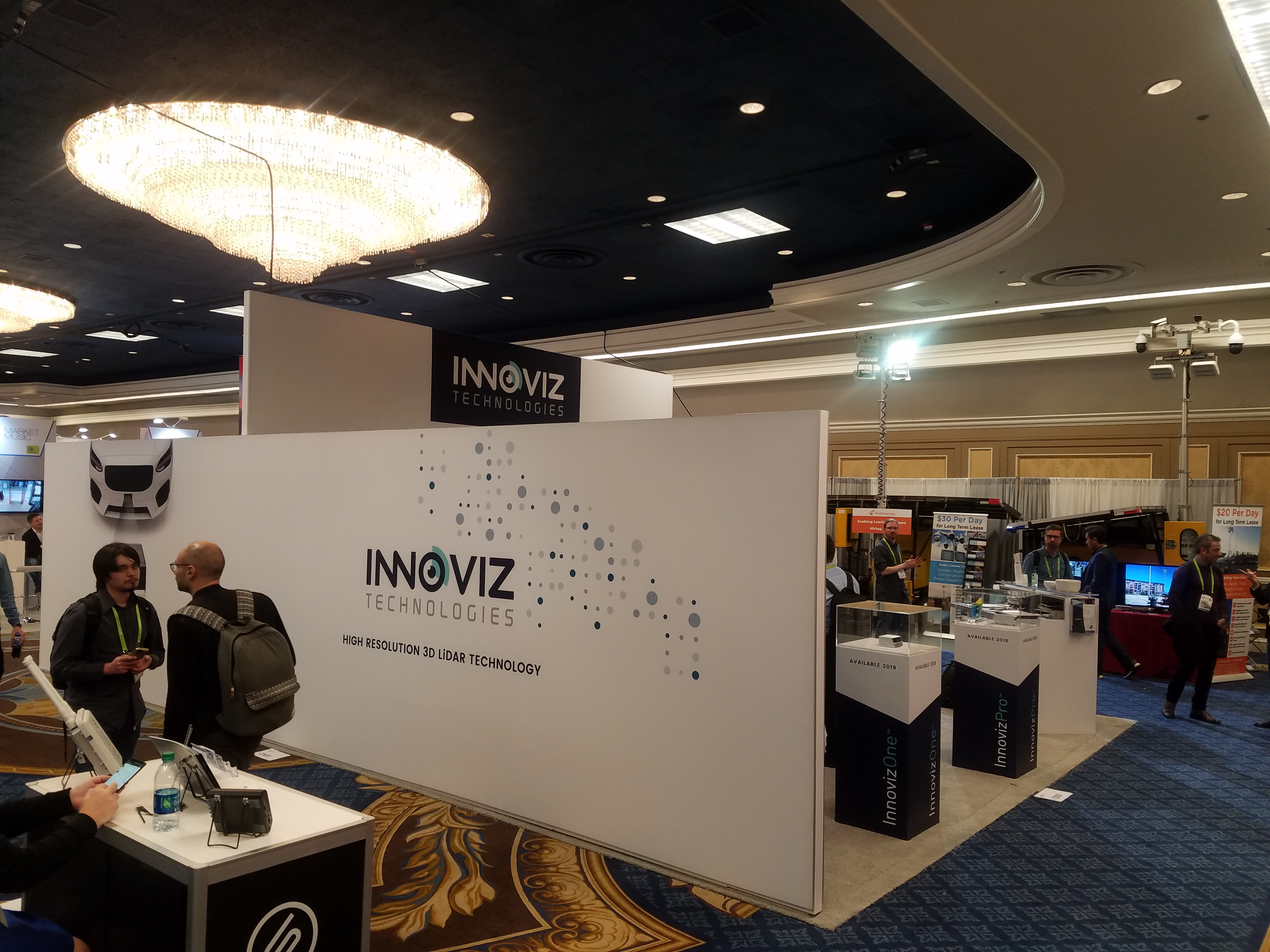
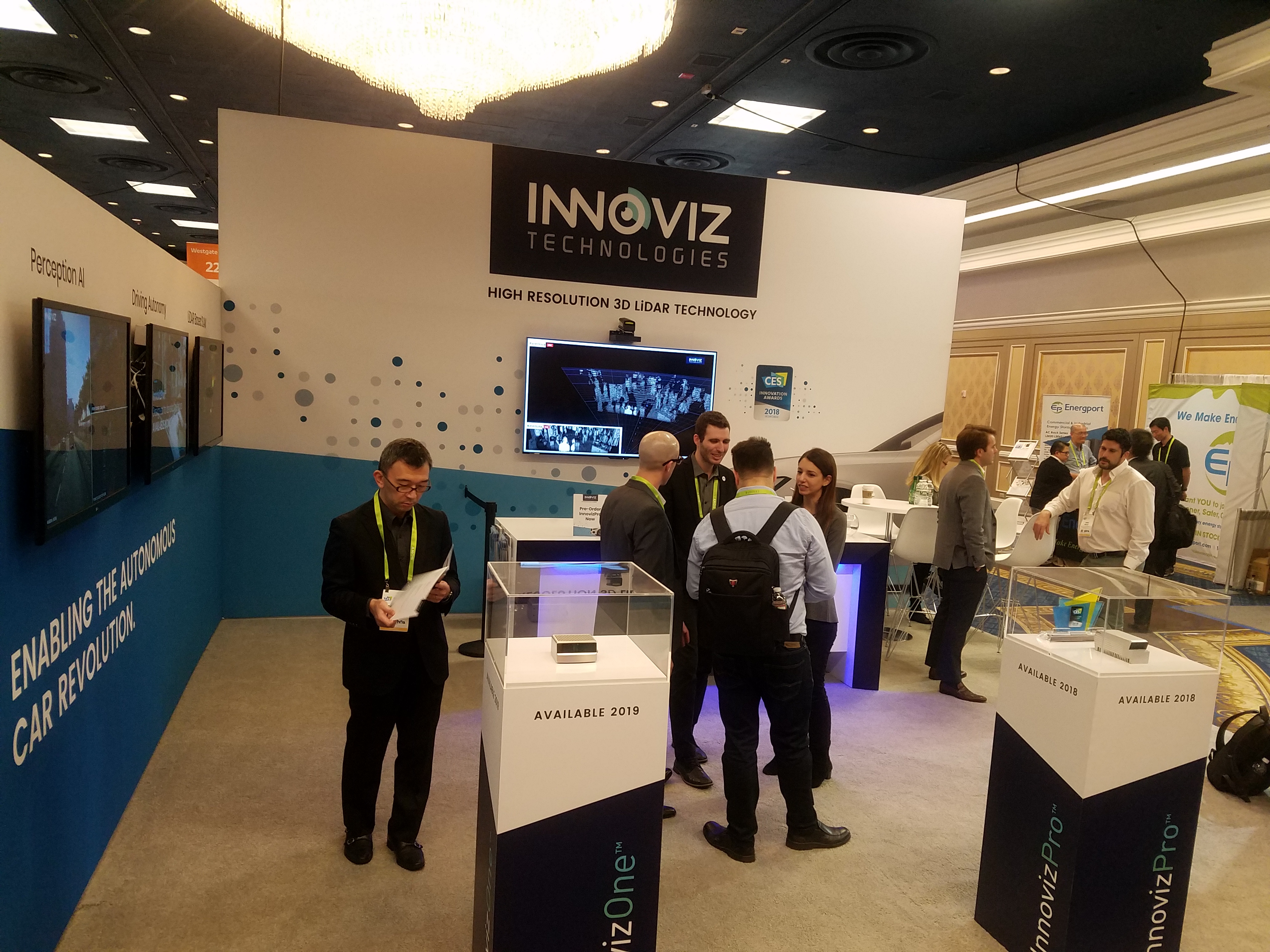
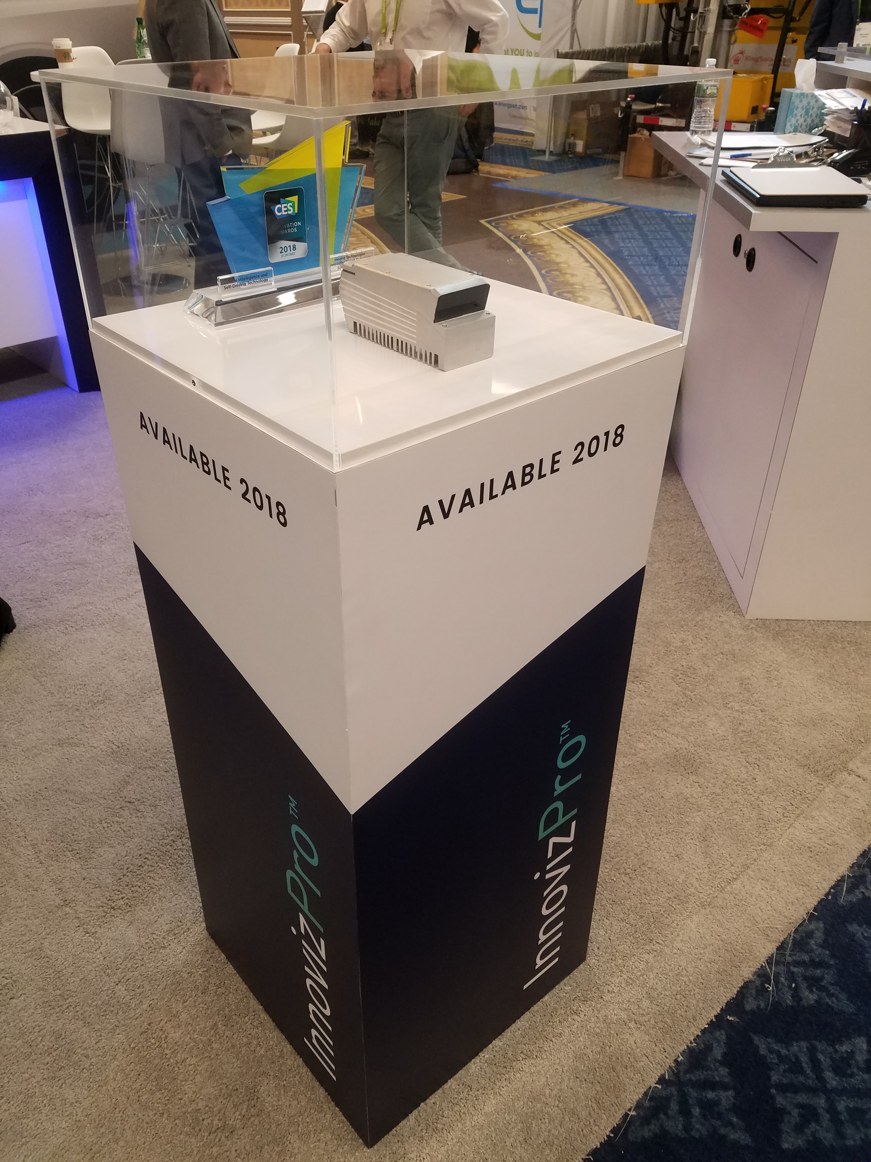
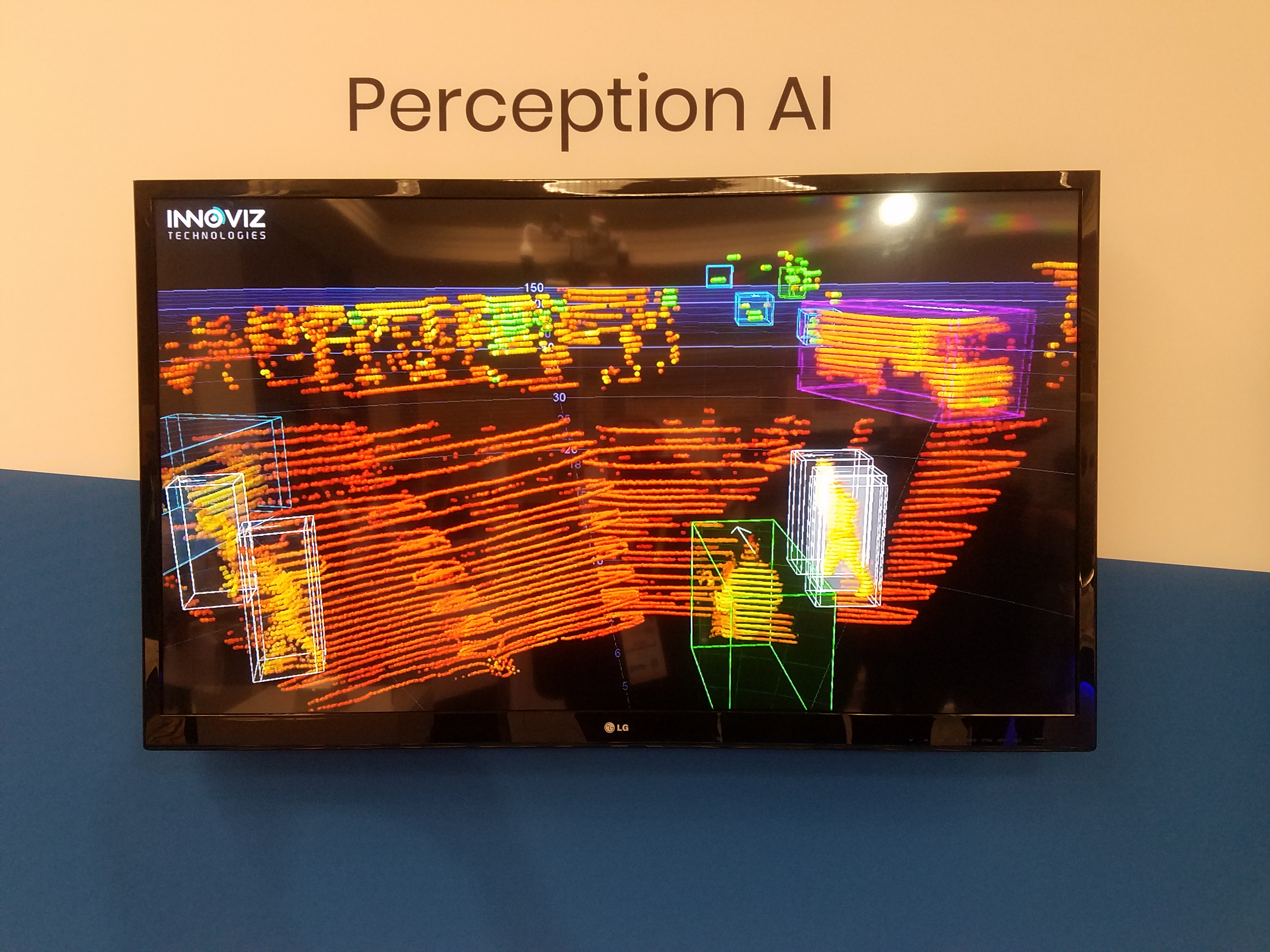
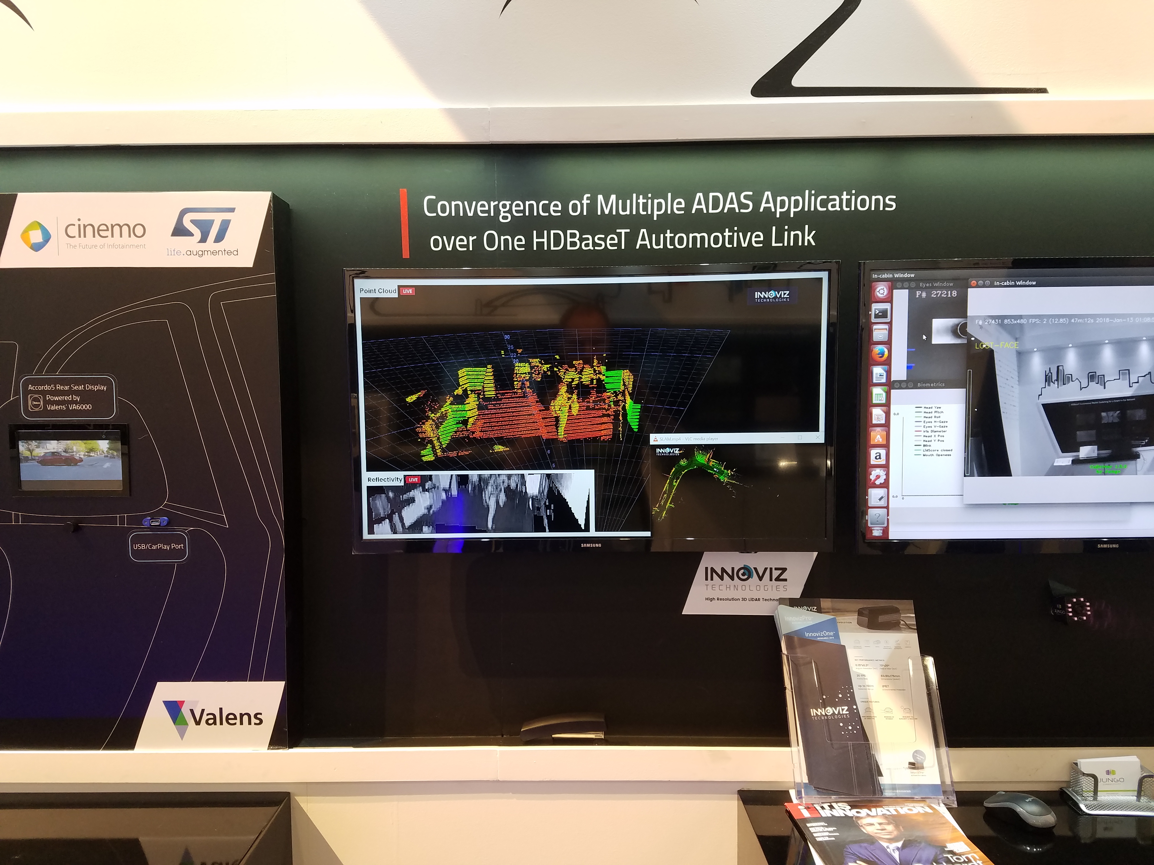
Innoviz Technologies
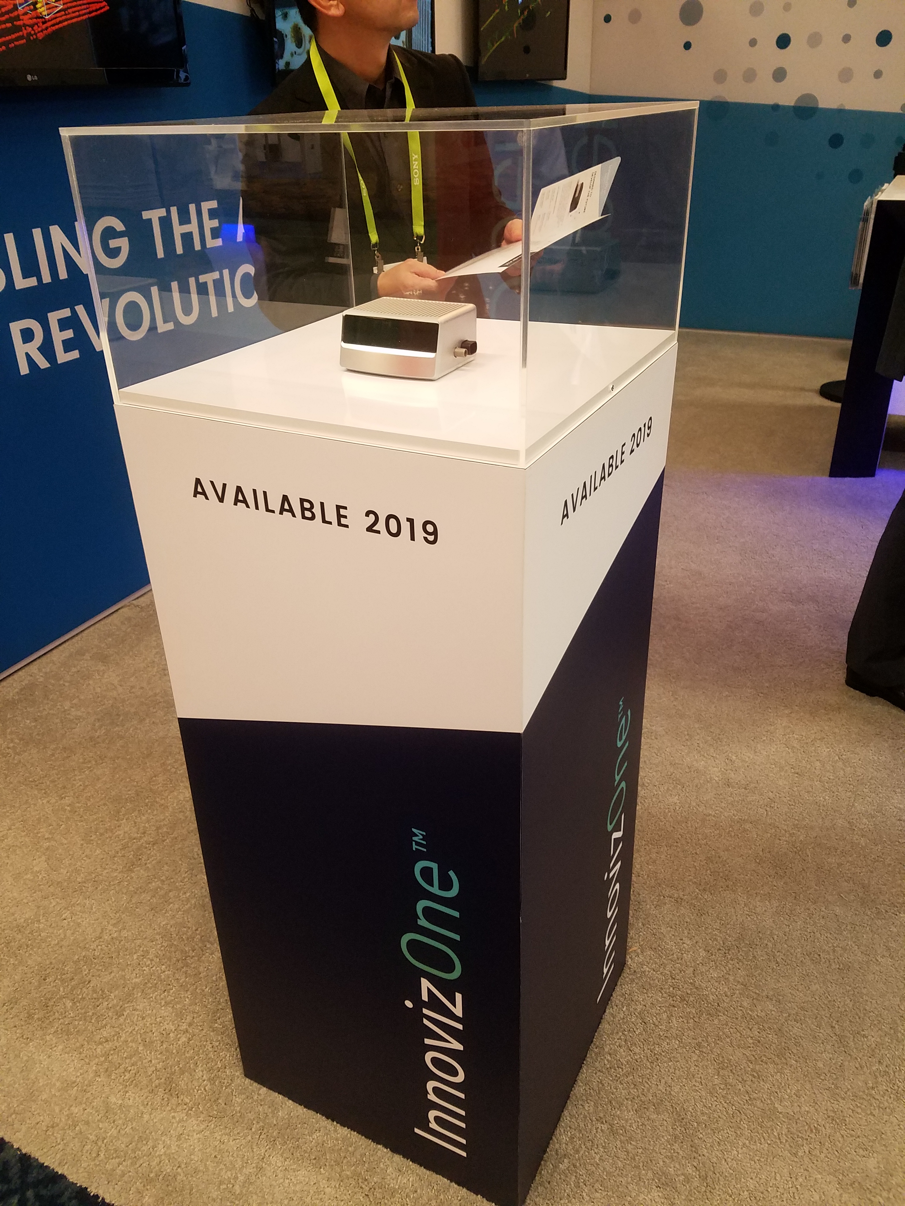
They were promoting their new LiDAR designs called InnovizOne and Innoviz Pro.
It’s a bit confusing because they have a product available now called “InnovizOne”, which they had running at their booth. Yet they also have a new product in development with the same name, which is an automotive-grade LiDAR with a wider rectangular casing like the Ibeo LiDAR.
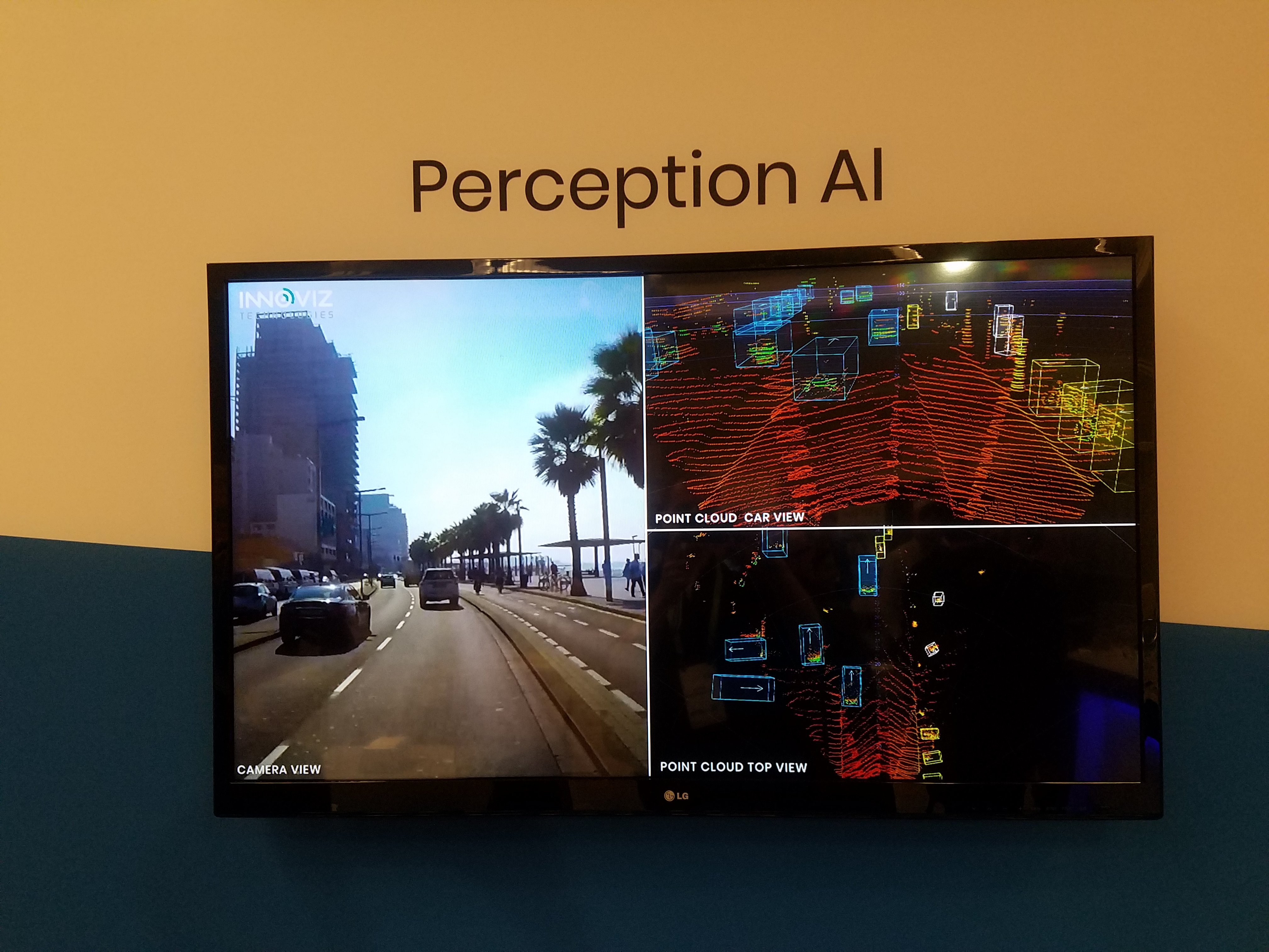
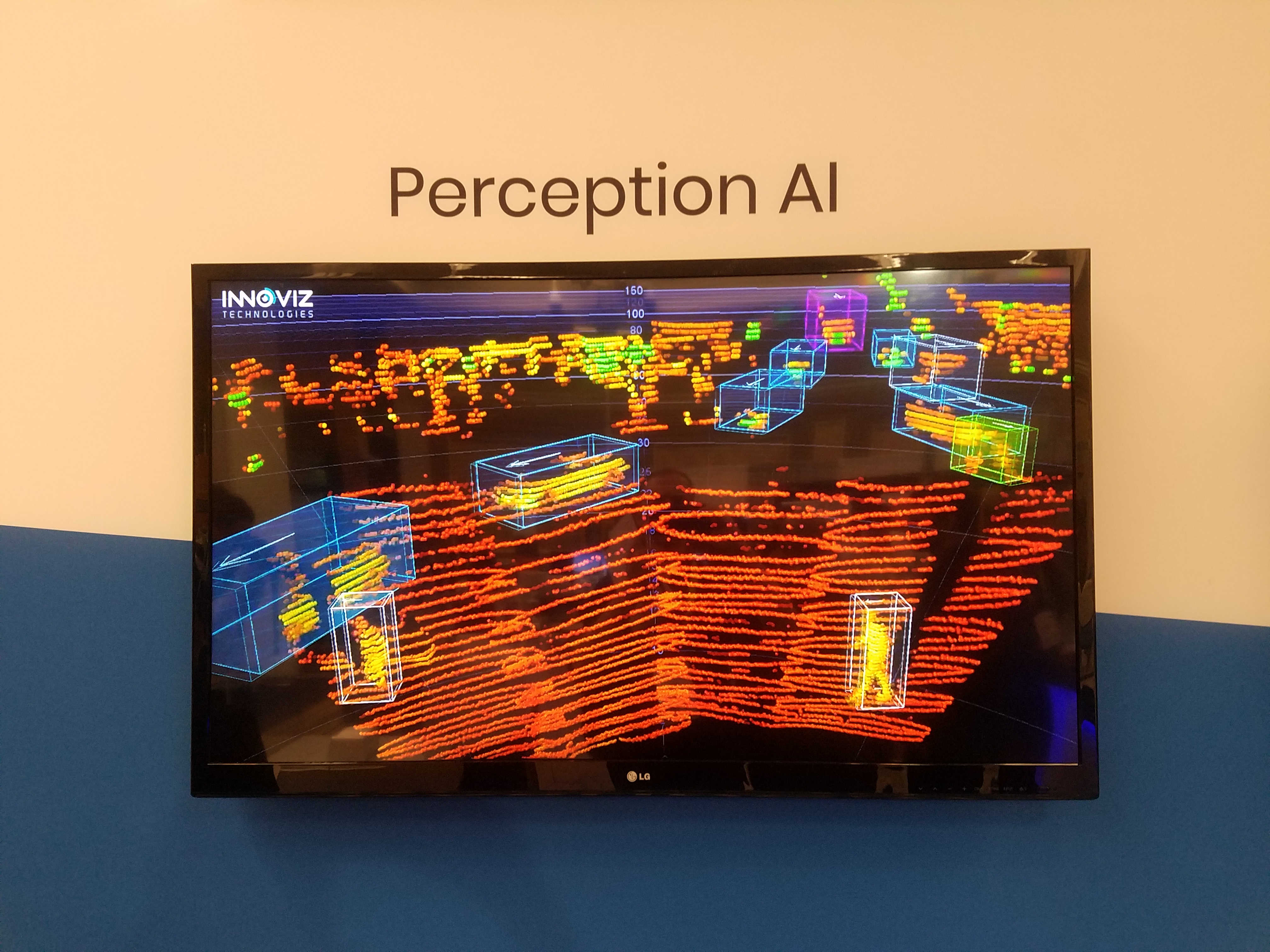
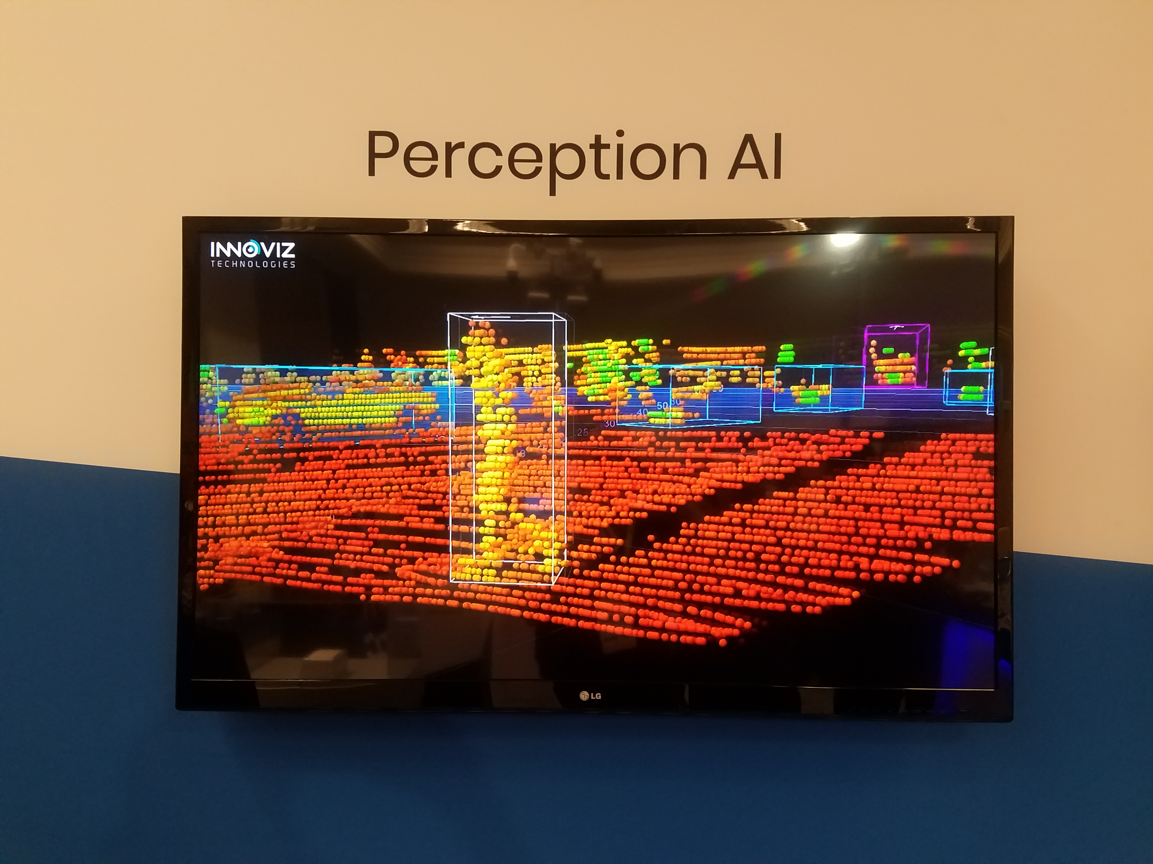
They had a couple of demo videos playing.
1. An object tracking demo. It shows the quality of LiDAR data captured from a moving vehicle and the output of a tracking system, with bounding boxes for cars, trucks, motorbikes and pedestrians. See Fig. 72-75 and Video 9.
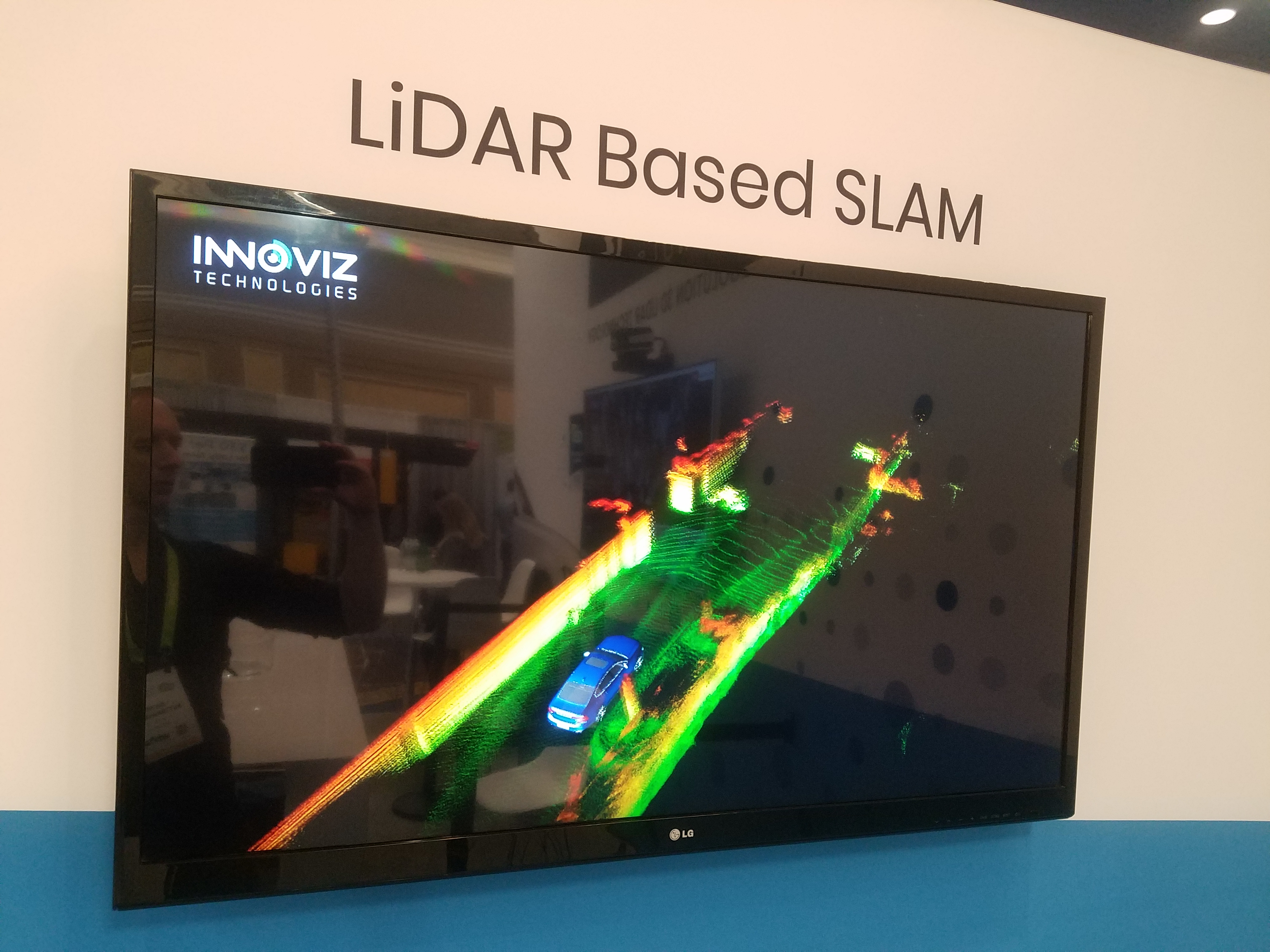
2. A SLAM demo. This showed a vehicle driving along and using the LiDAR data to do localization (Fig. 76). However, looking at the relative size of the 3D point cloud compared to the vehicle, the range of the sensor looks less than 200m.
Website: www.innoviz.tech
|
Fig. 68: |
Fig. 69: |
|
|
Fig. 70: |
|
|
|
Fig. 72: |
Fig. 73: |
Fig. 74: |
|
Fig. 75: |
|
|
|
Fig. 77: |
Fig. 78: |
|
|
Fig. 79: |
Video 10: |


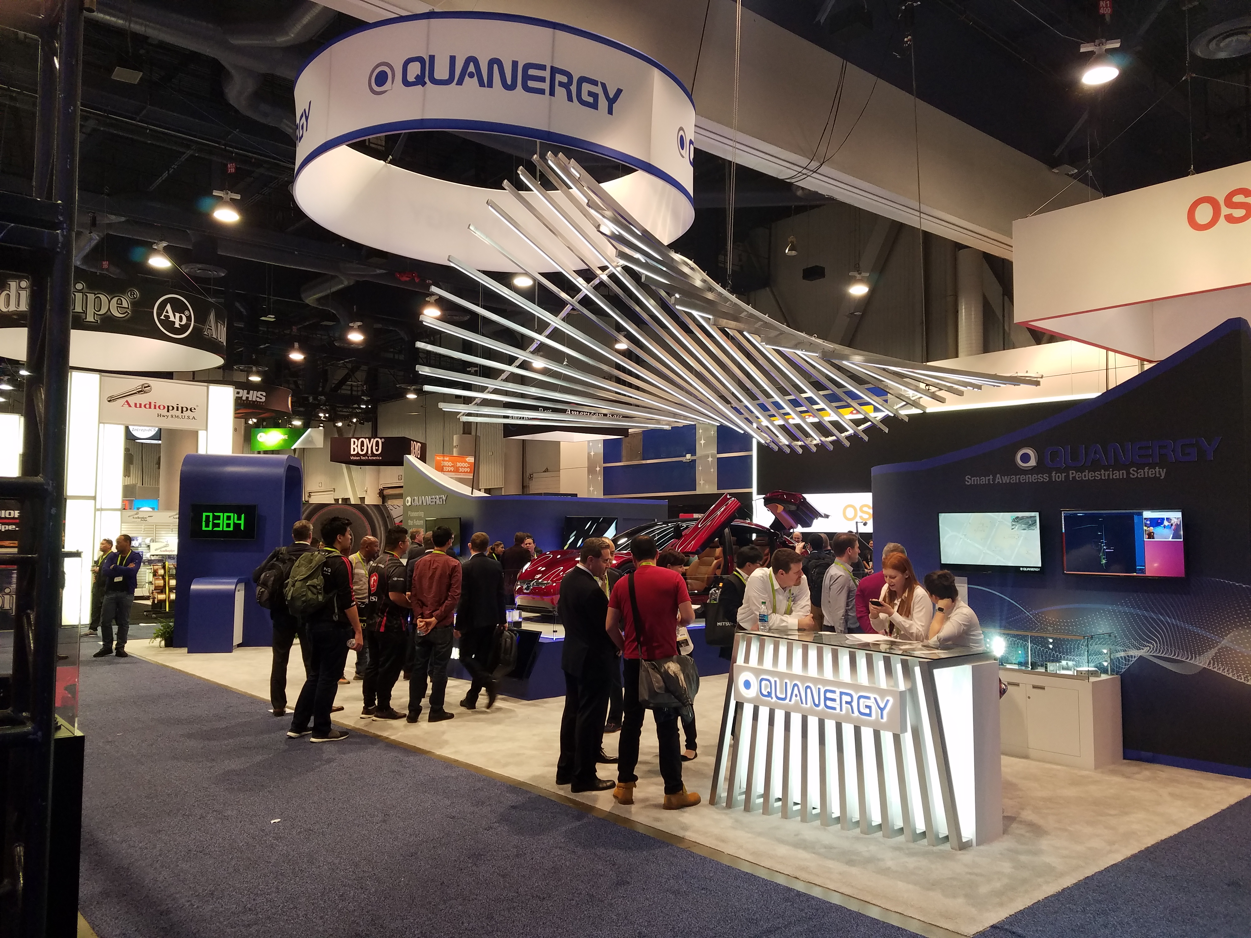
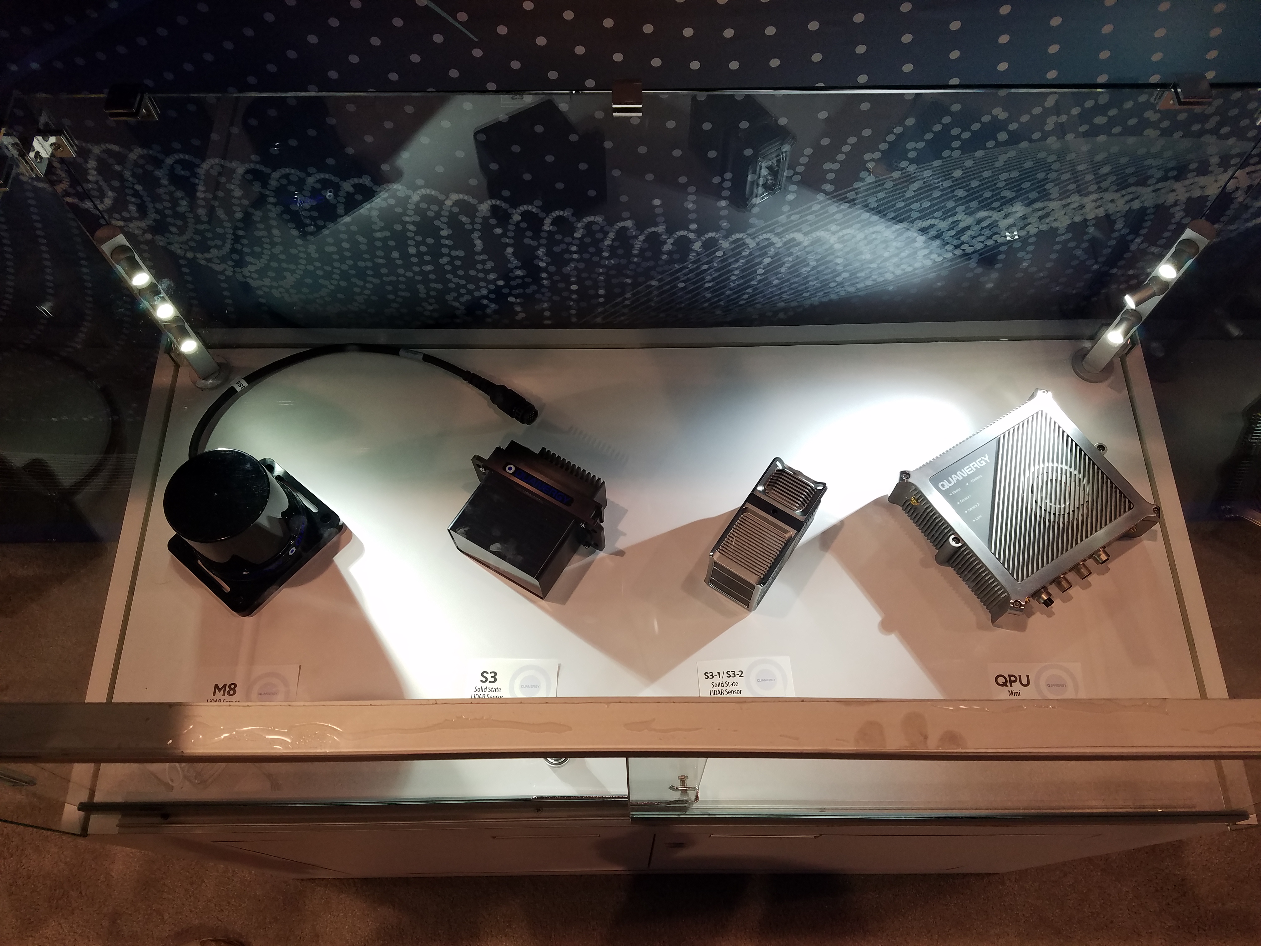
Quanergy
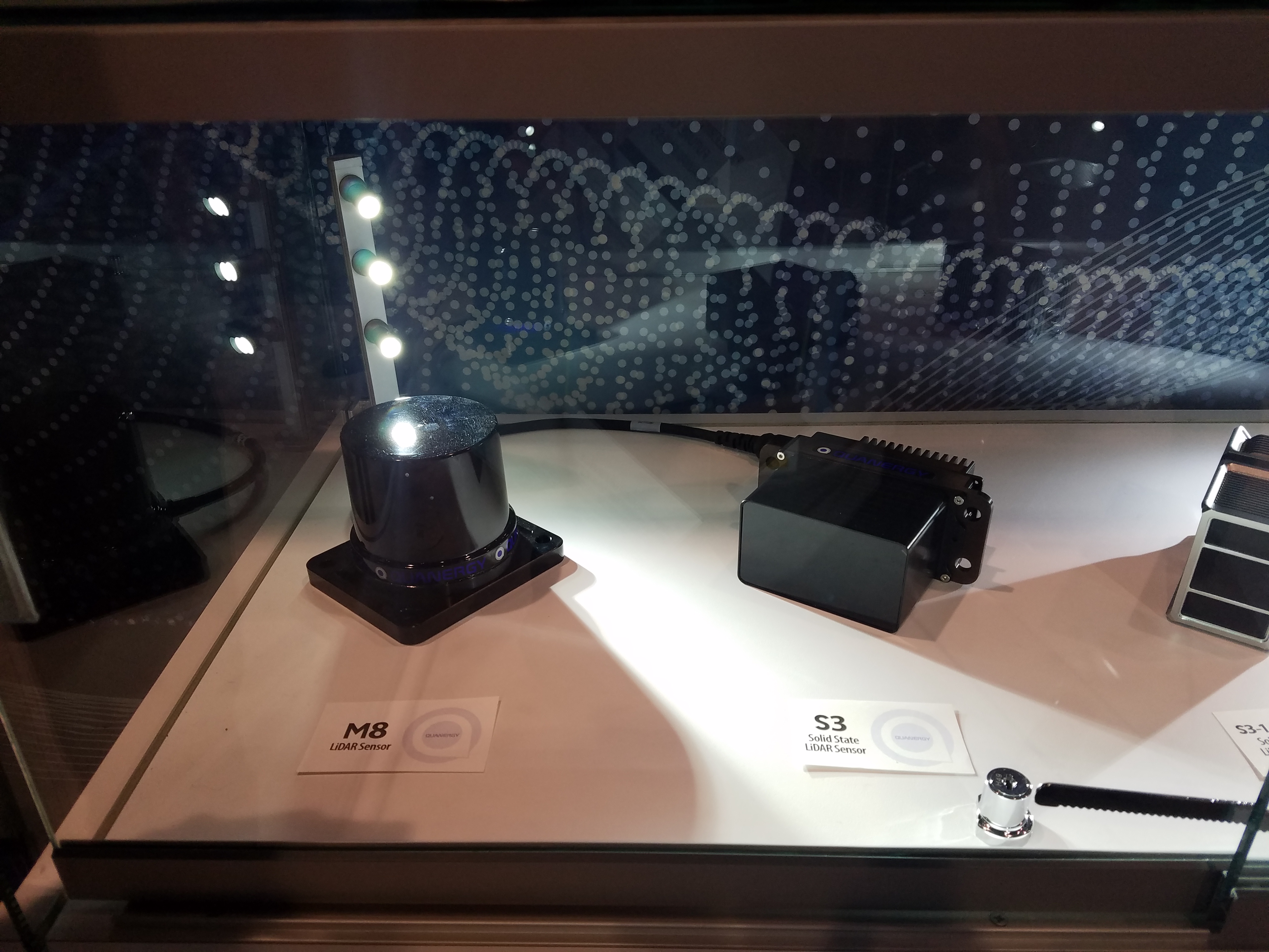
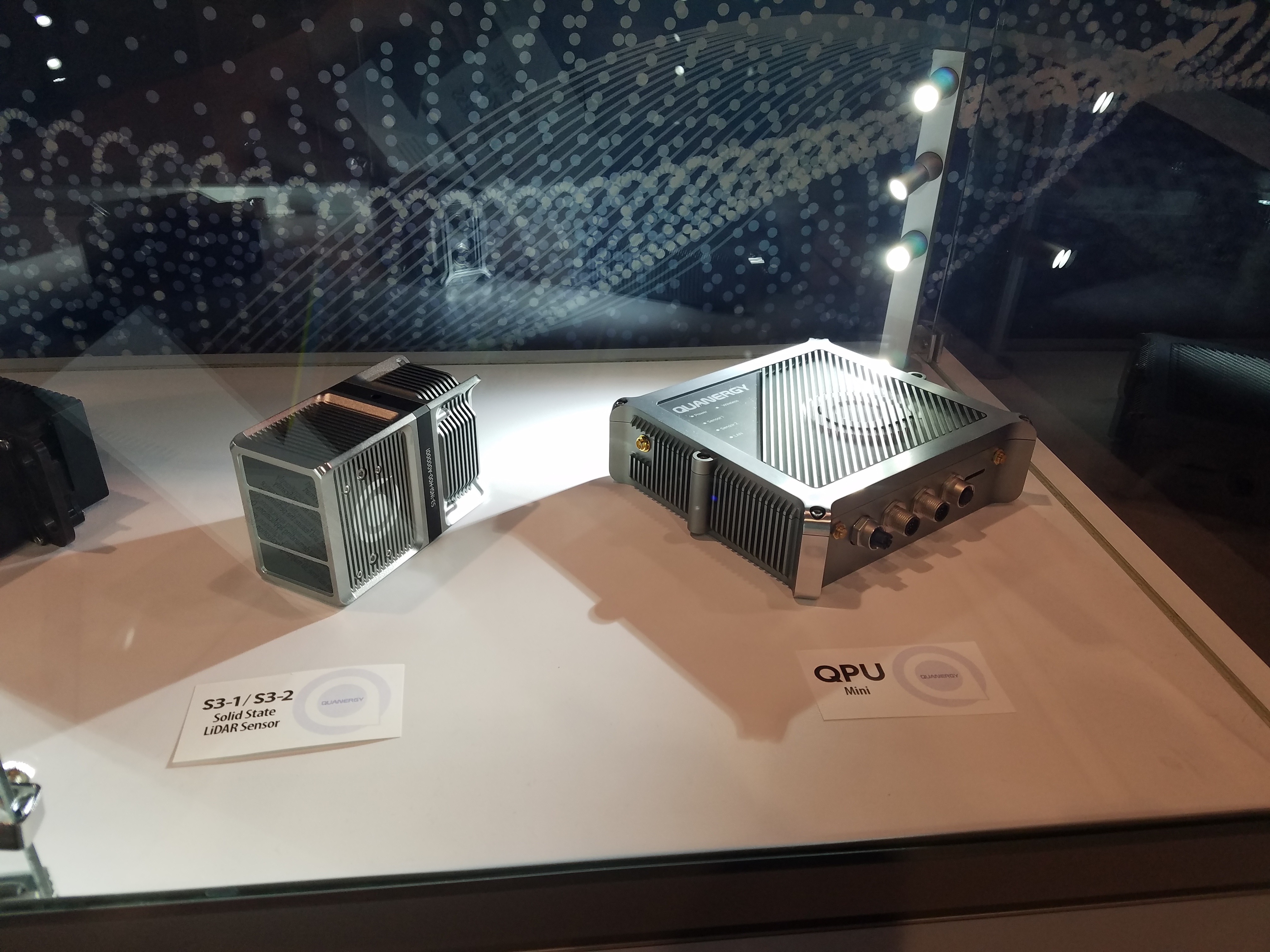
They were promoting their “M8” 360 degree LiDAR, as well as their “S3” and “S3-Qi” forward-facing LiDARS.
Unfortunately I couldn’t see any demo showing the live output of any of their sensors.
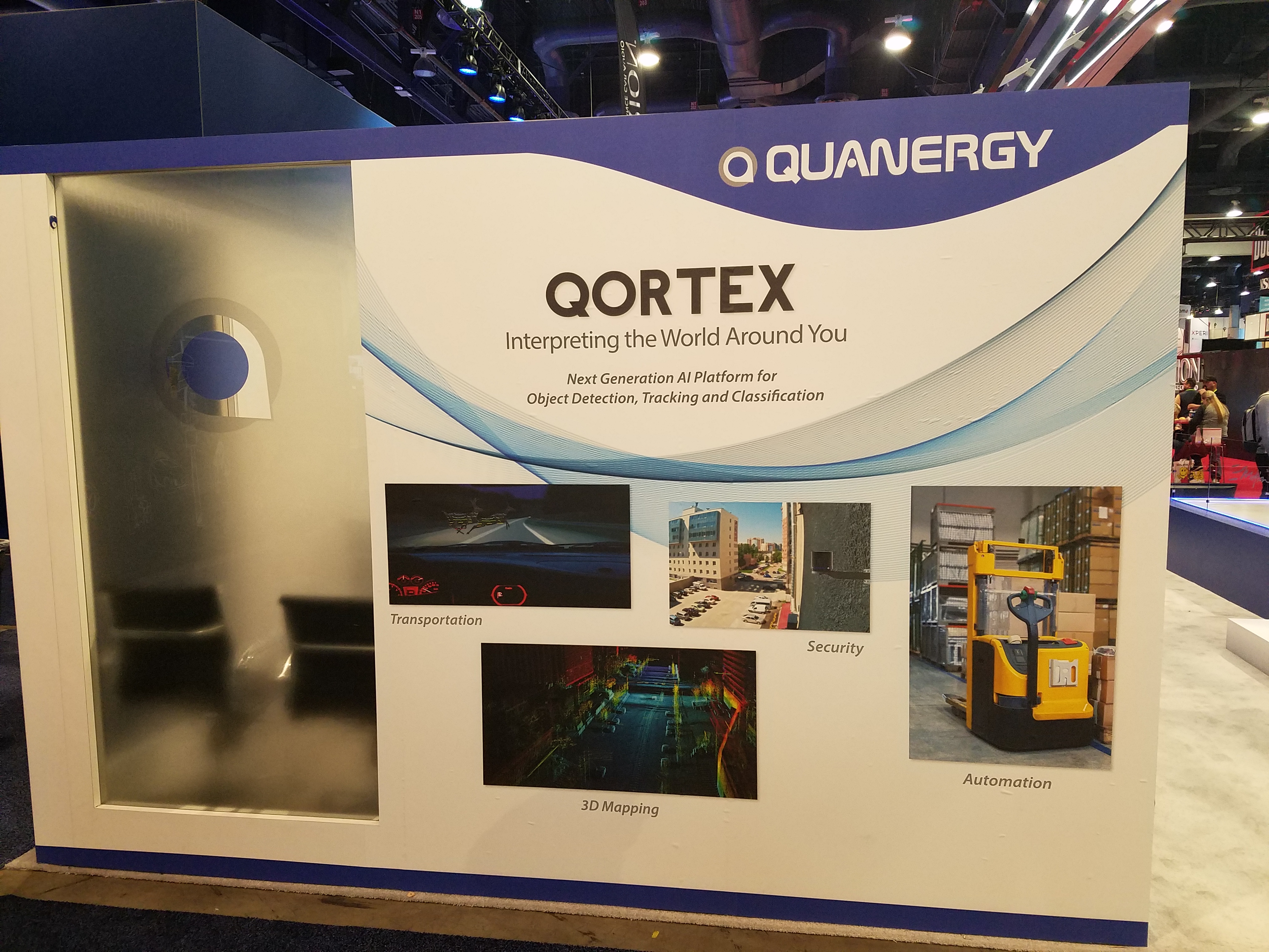
They also have a perception and tracking software system called Qortex, which came through the acquisition
of a product called OTUS People Tracker Software from Raytheon BBN Technologies.
Website: www.quanergy.com
|
Fig. 80: |
Fig. 81: |
|
|
|
Fig. 83: |
Fig. 84: |
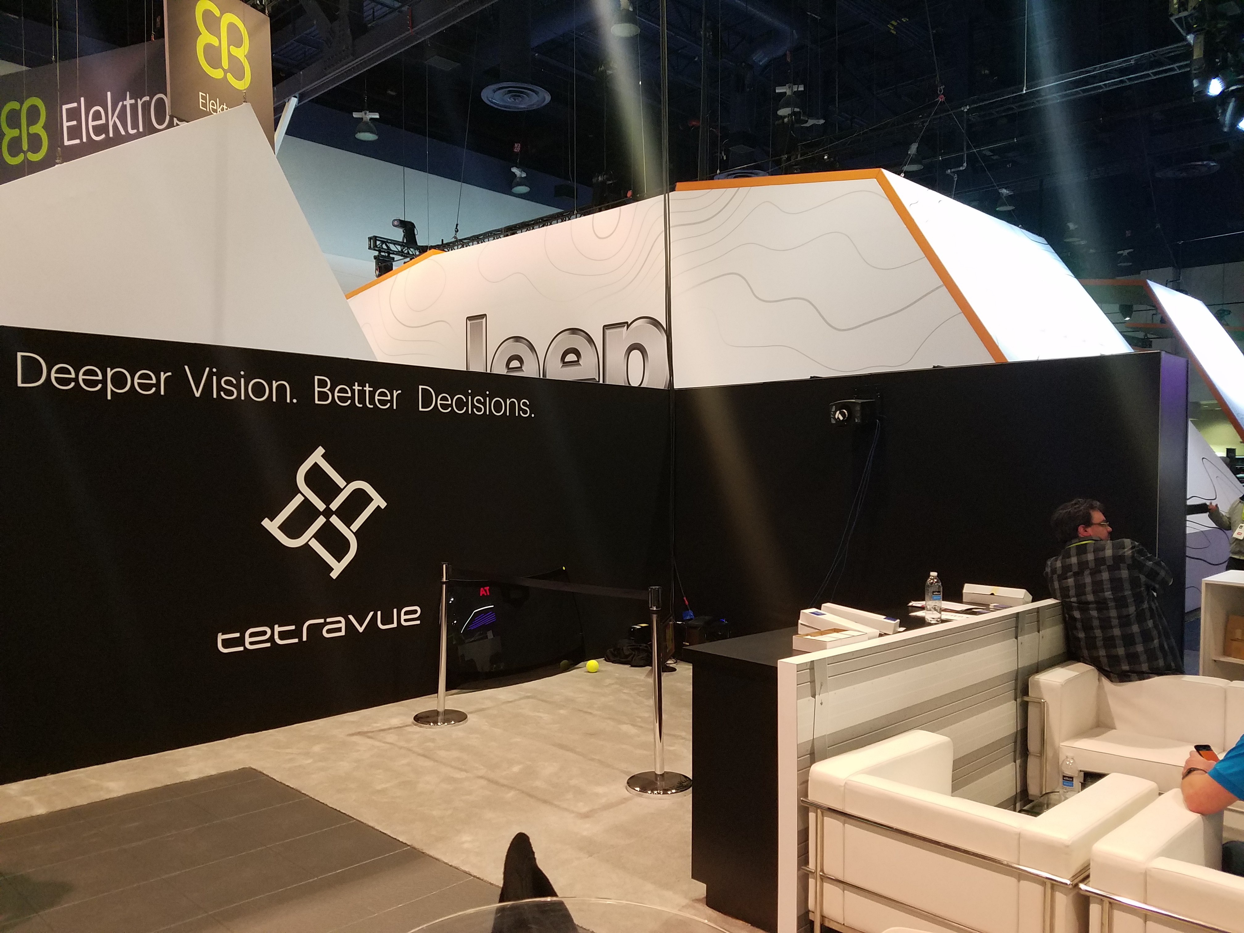
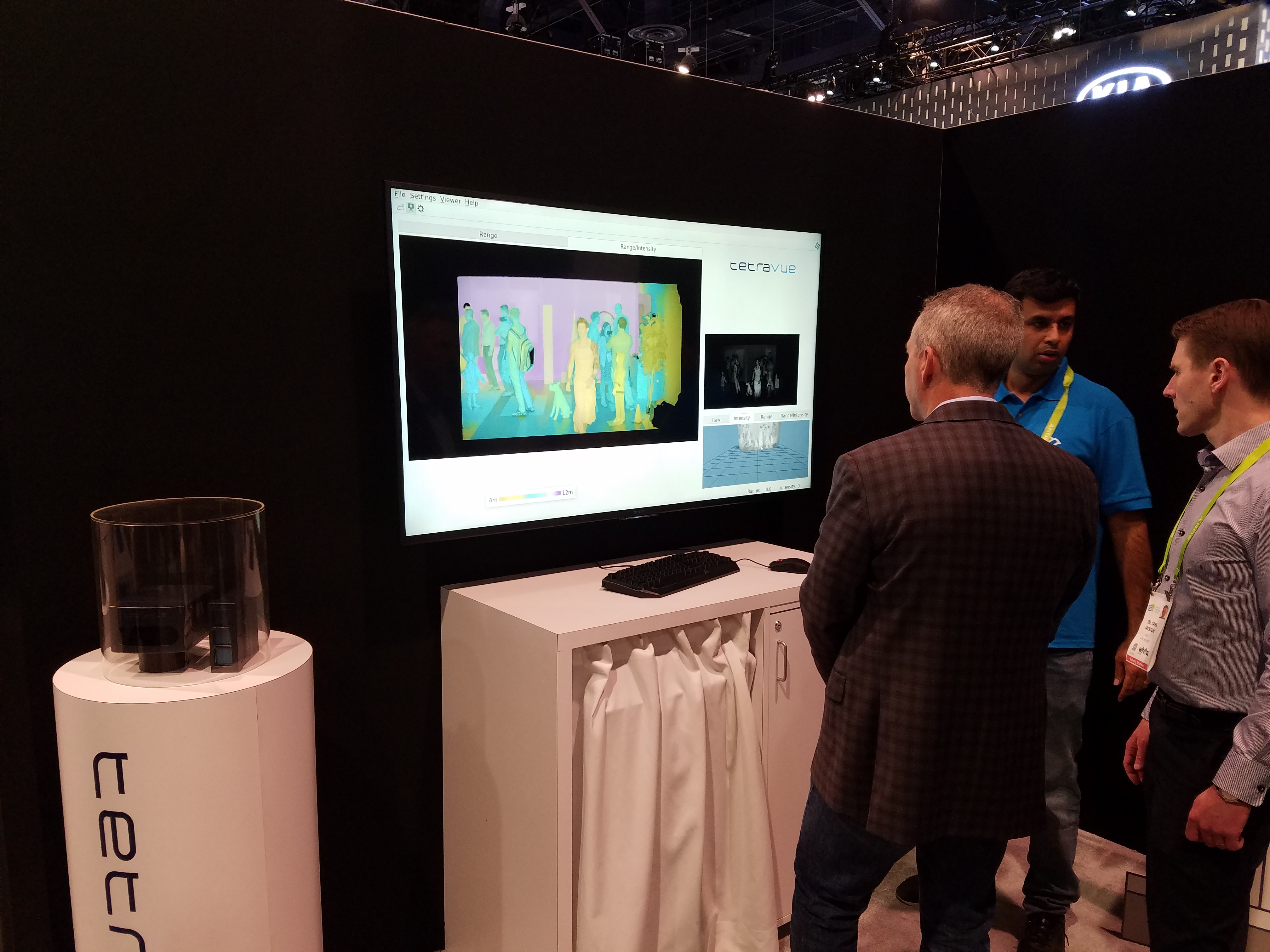
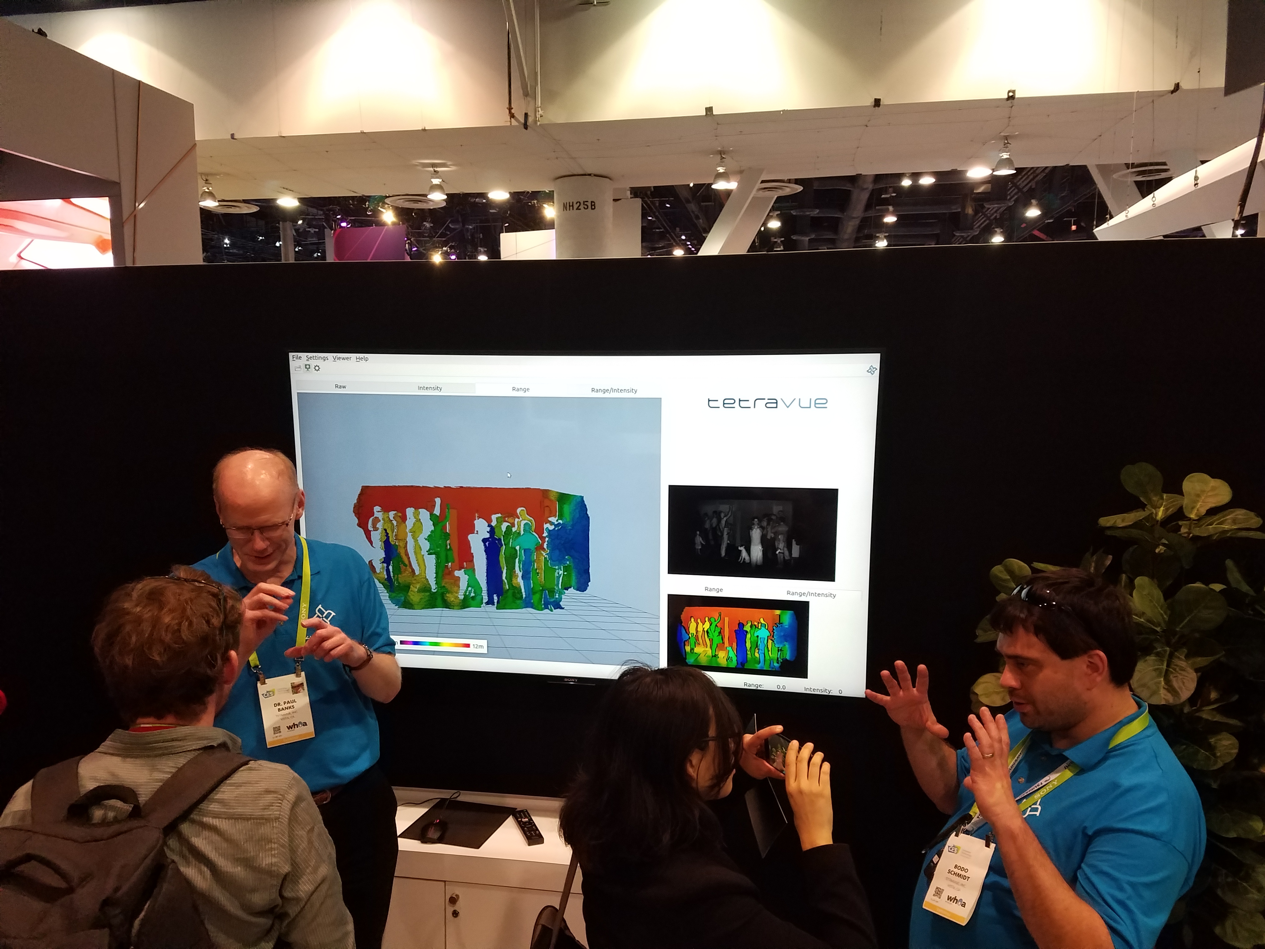
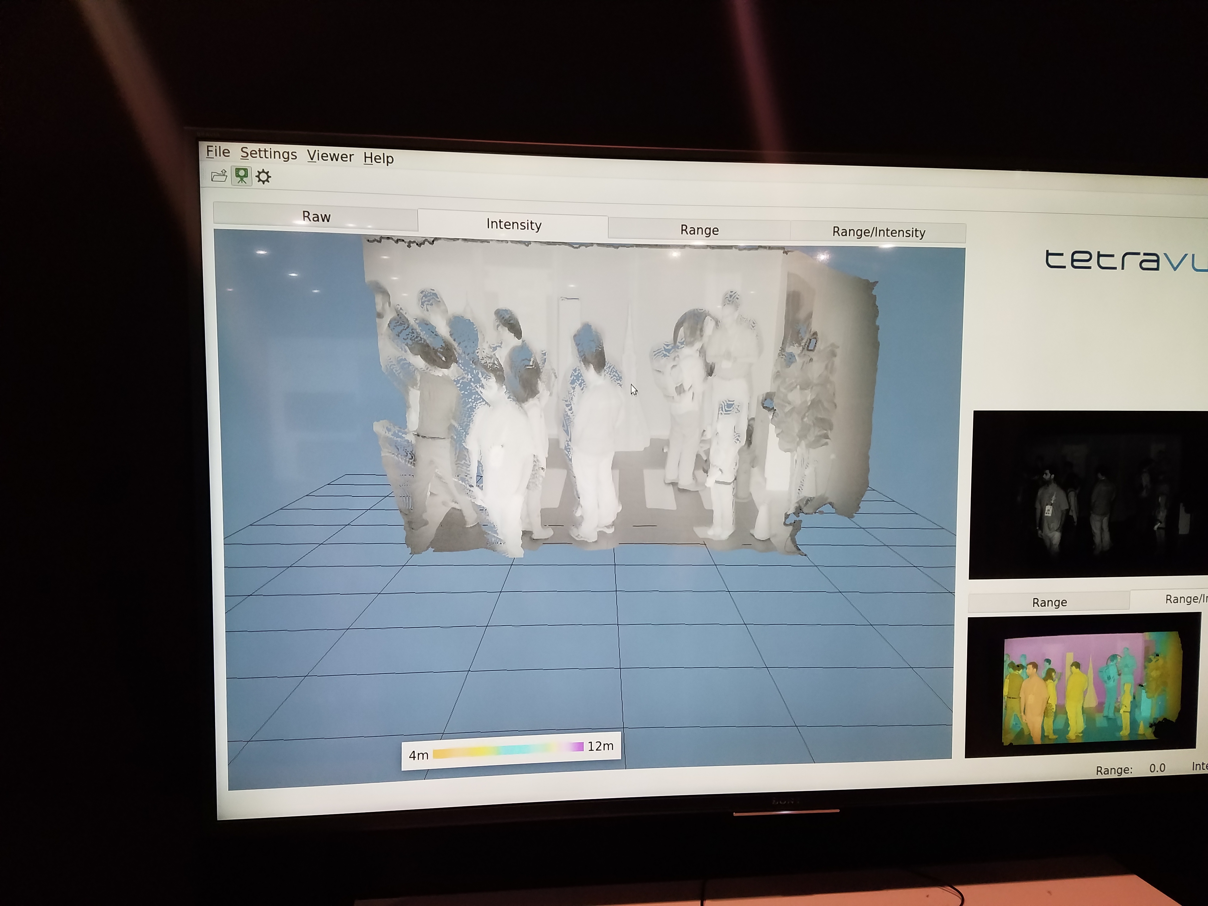
Tetravue
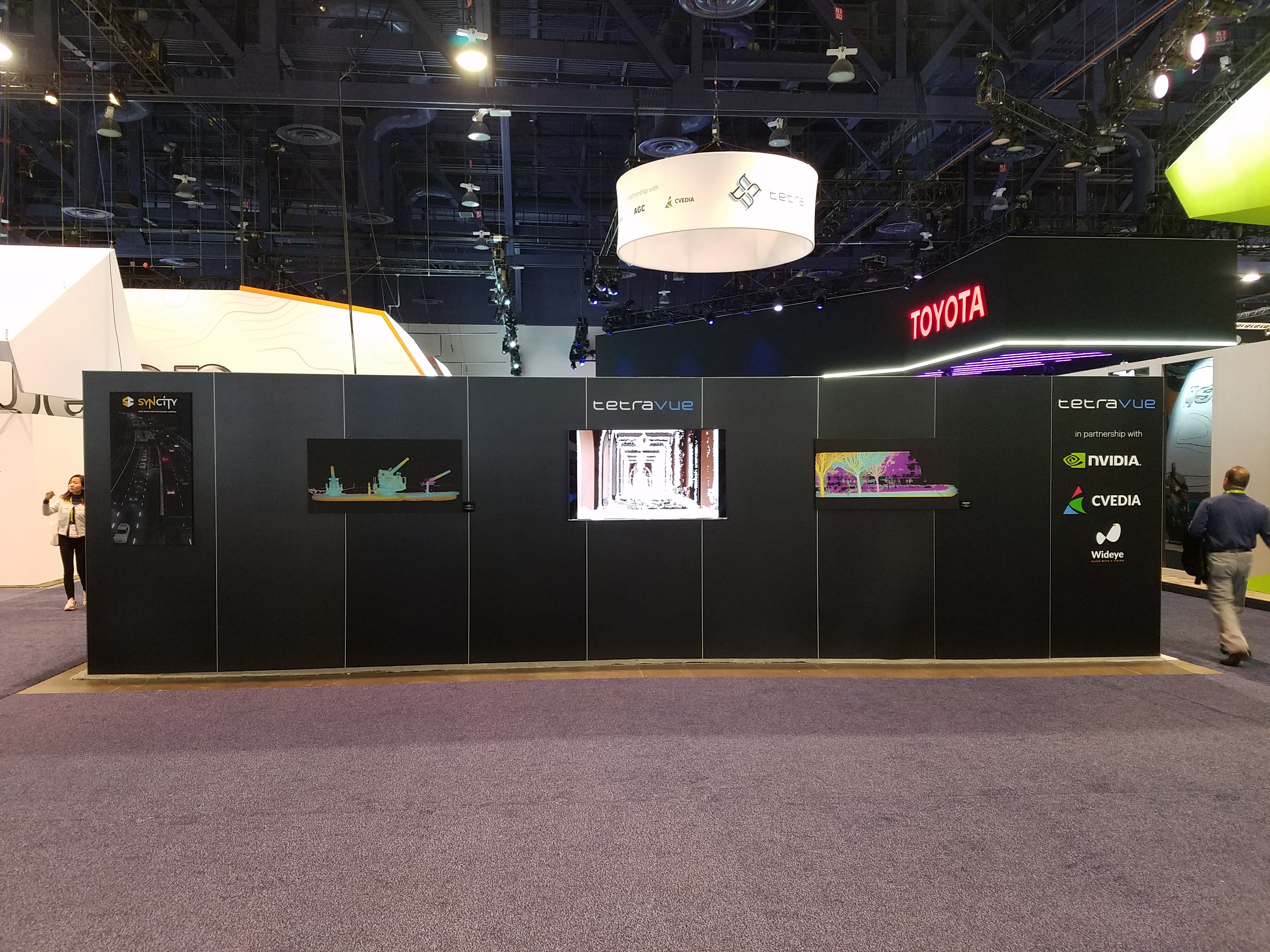
They were giving a live demo of their flash LiDAR technology that uses intensity-modulation to produce high-resolution range and intensity images. The prototype hardware is larger than the final product will be. The box is the size of a projector, with a large circular lens for the camera and 3 square-shaped IR light emitters on either side (Fig. 86). You can see the output from the sensor in Fig 87-89. Apparently their technology can also produce an RGB image but I didn’t see this.
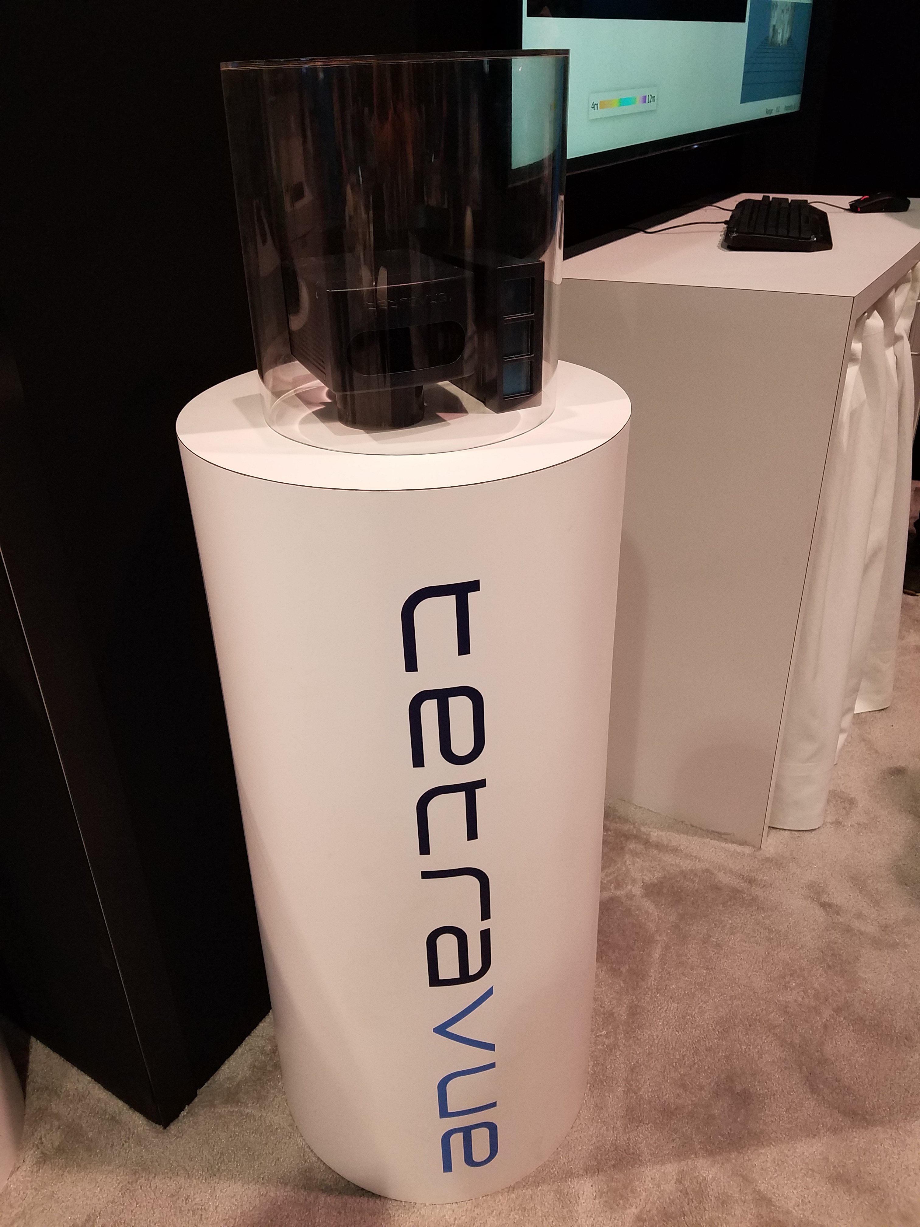
A non-working model of the final product was on display in a glass case, showing a 2-piece design with separate camera and light emitter (Fig. 90). They also had a model of a version designed to mount behind a vehicle’s windshield (Fig. 91).
Website: www.tetravue.com
In comparison to Tetravue’s intensity-modulation technology, other flash LiDAR sensors like the ASC (now owned by Continental Corporation) use ToF technology.
|
|
Fig. 86: |
|
|
Fig. 87: |
Fig. 88: |
Fig. 89: |
|
Fig. 90: |
Fig. 91: |
Video 11: |
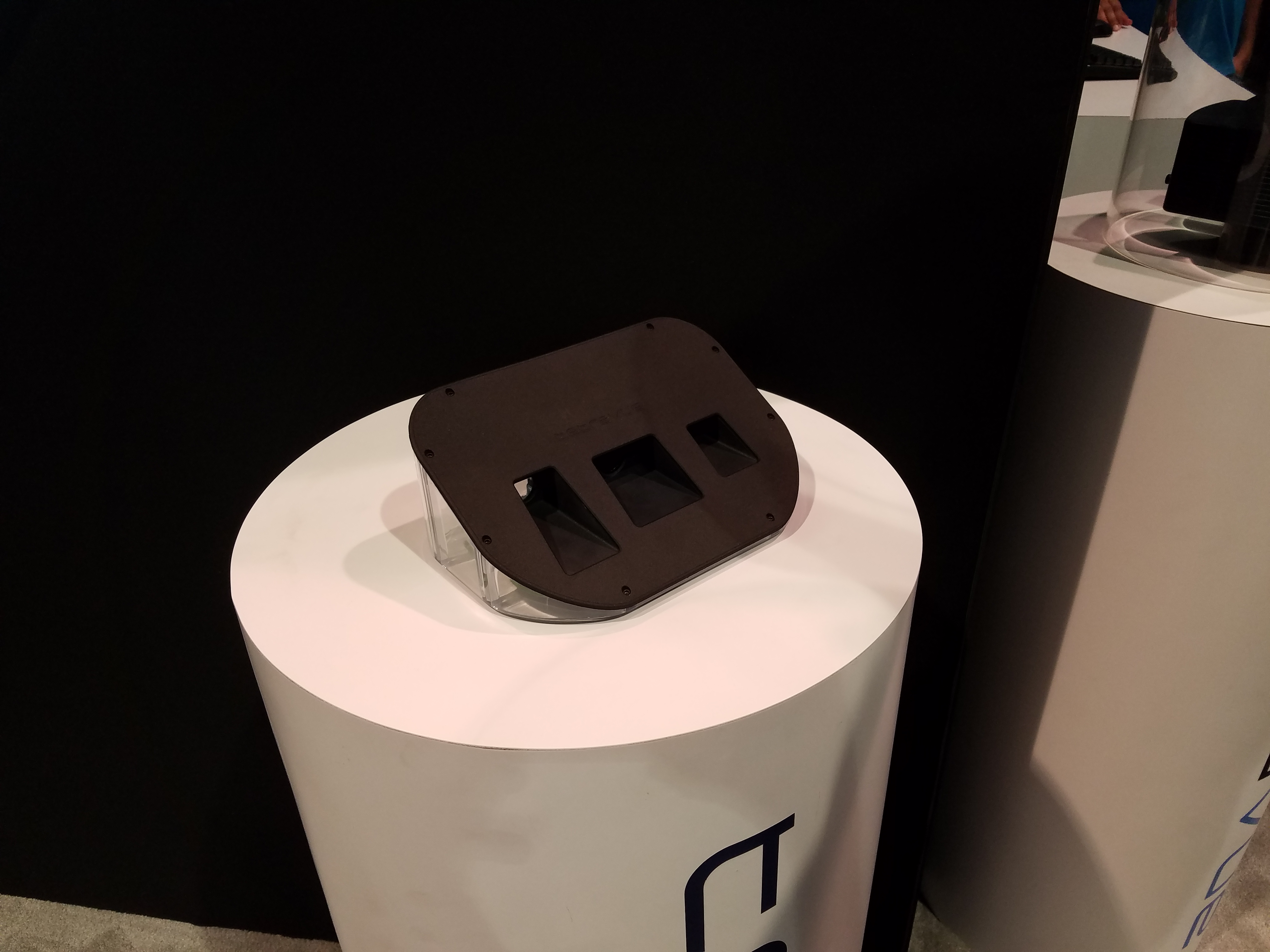

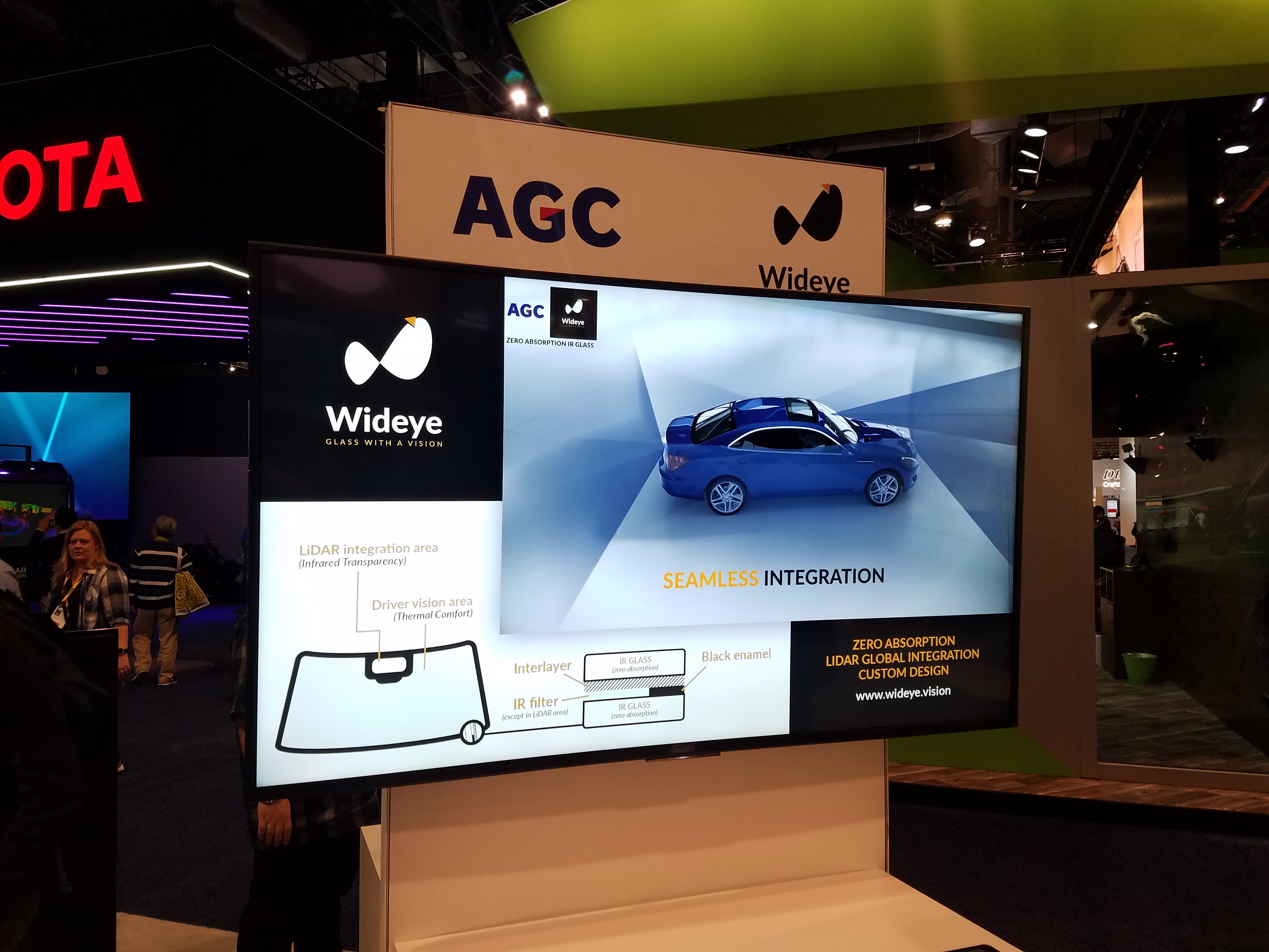
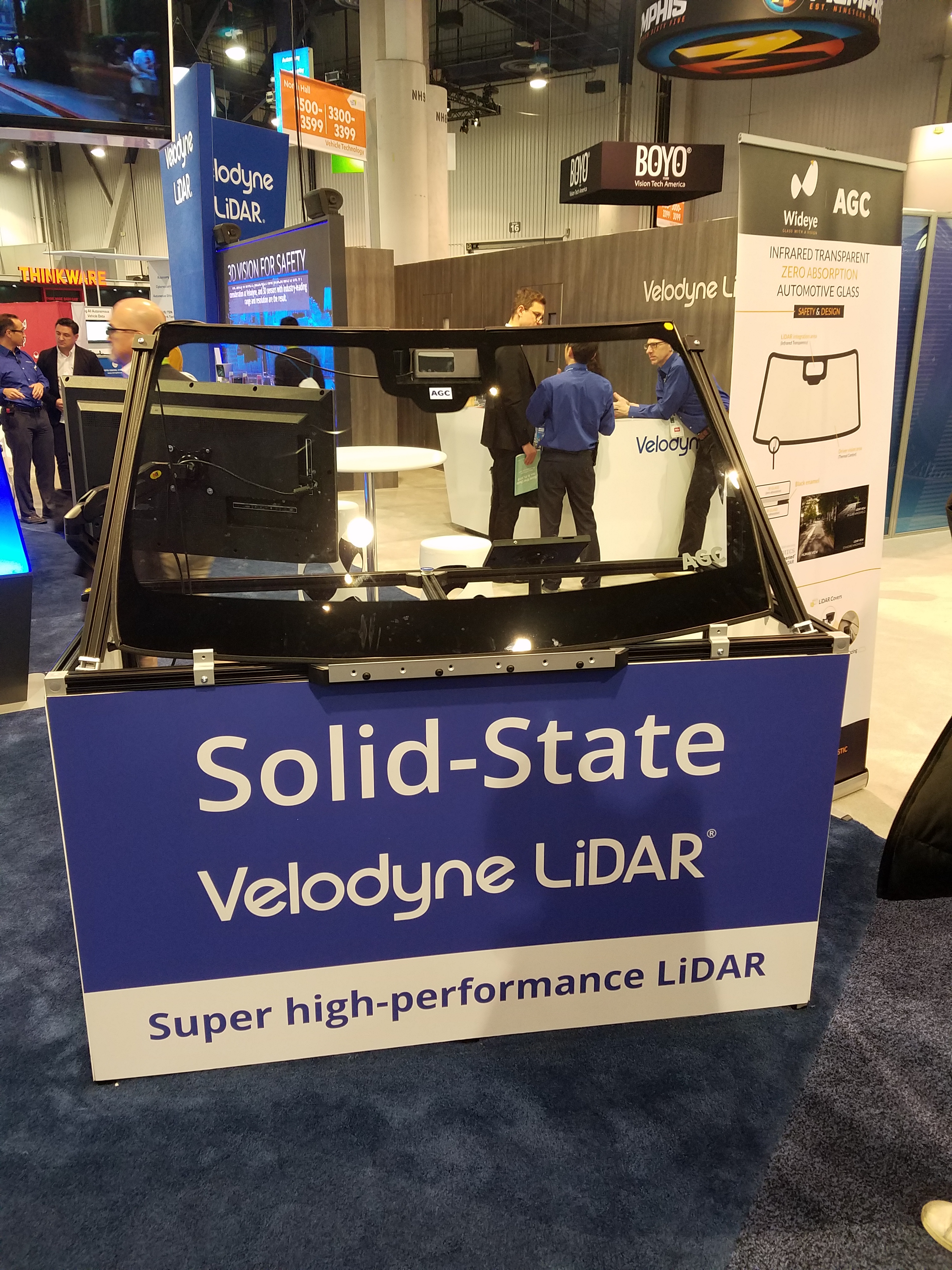
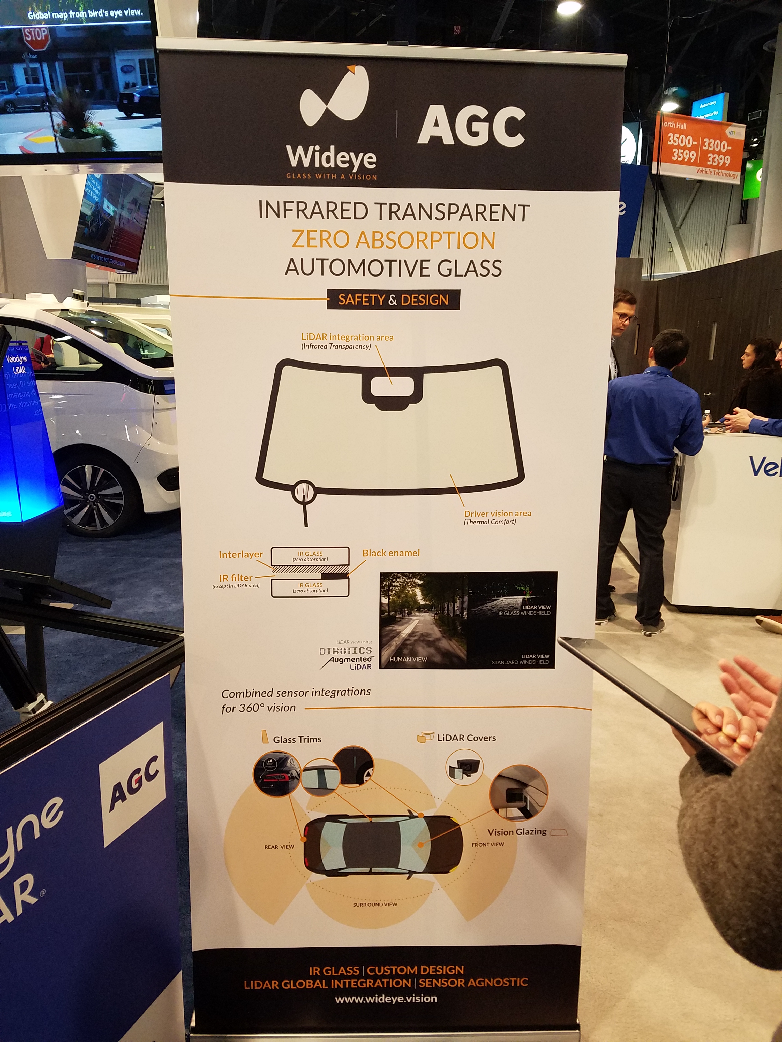
AGC/Wideye
For a fully integrated autonomous vehicle, it would be nice to put a camera or LiDAR behind the windscreen (windshield).
This company is producing custom glass that is transparent and non-absorbent in the IR spectrum.
Website: www.wideye.vision
|
Fig. 92: |
Fig. 93: |
Fig. 94: |
Other companies
Here’s a few other companies in this space to watch:
| Innovusion www.innovusion.com |
| TriLuminar Corp. www.trilumina.com |
| Cepton www.cepton.com |
| Benewake www.benewake.com/en/ |