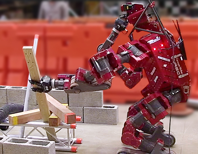
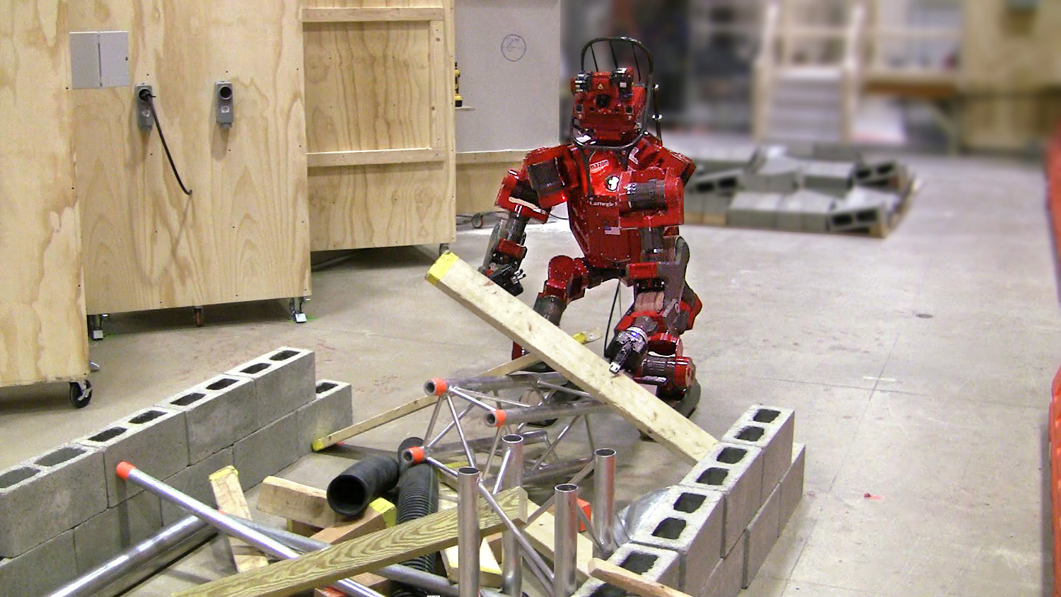
Clearing a pile of debris is similar to the problem of pick-and-place of unknown objects in clutter, in that the objects are unmodeled (no 3D mesh is available). However the scenario is more complicated because the objects are stacked and possibly entangled, which requires solving the manipulation problem. This means that the objects must be grasped both in a specific sequence and extracted from the pile (moved to the post-grasp pose) along a particular trajectory. Fig. 1 shows the CHIMP robot grasping a piece of lumber (or timber) that must be extracted lengthways to free it from the other objects.
This project was to research and implement a system for autonomous grasping of unknown objects. The system was tested on CHIMP (CMU Highly Intelligent Mobile Platform), a mobile manipulator designed to operate in hazardous environments [1]. During the DARPA Robotics Challenge the operator was able to drive the robot to plow through (bulldoze) a pile of light debris. However it was slow and tedious for the operator to manually tele-operate the robot’s arm to grasp individual objects.
Robot platform:
The robot has two 7-DOF position-controlled arms, each with a 3-fingered gripper. The Robotiq gripper was modified for increased durability, including tougher internal gears and wiring re-routed through the wrist. The arms’ positional-repeatability is generally sufficient for grasping. However each joint has a torque-tube and clutch on the output shaft that can stretch or slip, thus affecting any prior calibration.
Approach:
The overall problem-solving or task planning is performed by the human operator, who commands the robot to compute specific motion plans. This is quicker than trying to solve the combined manipulation planning problem automatically, which requires both a symbolic representation of how the objects are arranged [2] and a logic-based planner [3-4].
Perception is handled both by the human operator and the robot. The robot captures a full LiDAR scan of the environment which is used to accumulate a dense point cloud, for object detection, and to generate a voxel grid for collision-avoidance with the environment. The robot’s arms are positioned to the side, to prevent casting shadows on the point cloud.
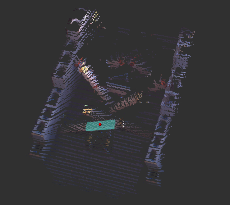
The operator views the scene via a 2D camera image or colorized 3D point cloud. Using the mouse, the operator clicks on a point in the camera image to select which object is on top of the debris pile, is easiest to move, or closest to the robot. This 2D point is projected onto the 3D point cloud (Fig. 2) and a spherical area of points are cropped-out.
The object detection algorithm uses the assumption that most of the objects are either cuboid-shaped or cylindrical. Even if this is not true, the Robotiq gripper works best for performing “power” or “parallel” type grasps. The human operator specifies the pre-grasp posture of the 3 fingers and then the gripper controller closes the fingers until motion ceases. This means that, in practice, both cuboid or cylinder-shaped objects can be grasped simply by closing the fingers. It would be more rare to encounter an object that requires a “sphere” or “precision” type grasp.
Initially the approach for object detection was to iteratively detect all shape primitives within the point cloud using RANSAC [5]. First planar surfaces, then perpendicular planes, then cuboid shapes, and lastly cylinder shapes. This works reasonably well in a dense point cloud but it’s time-consuming to compute and the result is dependent on some tunable parameters. Also, the LiDAR point cloud is non-structured with an unorganized order to the set of 3D points. RANSAC might randomly select points where it’s physically impossible for them to be part of the same object. In contrast to this, more efficient algorithms leverage the structured order of points output from TOF (Time of Flight) sensors like the “Kinect”, using region-growing or other heuristics. Therefore the final approach was to try to only fit one geometric primitive model to a small region of the scene.
 |
 |
The operator selects either “cuboid” or “round” (cylinder) from the user interface and then clicks once in the camera image. After cropping a small group of points, PCA (Principal Component Analysis) is used to find the dominant axis. This is based on the assumption that most debris objects are longer than they are wide. If PCA does not find a major axis then further input from the operator is required. The normal direction vector of each point is computed using local patches. The algorithm tries to fit a cuboid (modeled using two perpendicular planes) or cylinder using RANSAC. The object pose sampling for model-fitting is constrained such that a surface must be coincident with the point clicked by the operator (Fig. 2), and the object is lengthways along the major axis of the point cloud.
Grasp planning is shared by the human operator and the robot. To grasp a cuboid or cylindrical object with a “power” grasp, the grasp pose must be somewhere within a 90 degree rotation angle around the length of the object, facing towards the robot. The operator selects an initial seed for the pre-grasp pose, being “top down” or “front”. The algorithm generates a sequence of grasp pose candidates, starting from the recommended (seed) pose and rotating 90 degrees around the object. Also it is difficult for the robot to determine how best to free the object from the pile because the LiDAR doesn’t capture if part of an object is hidden by other debris. The operator chooses a “grasp action”, such as “lift vertical”, “pull towards robot” or “slide out lengthways”. The grasp planner sequentially tests each pre-grasp pose and grasp action in order to find the first viable solution. The drop zone (final goal region) to release the object is anywhere to the side of the robot.
Motion planning for the gripper and arm is performed by the robot using a sequence of sampling-based motion planners.
This meta-plan consists of the following actions:
- Move gripper from current pose to pre-grasp pose.
- Move gripper from pre-grasp pose to grasp pose, constrained along a line.
- Close gripper fingers.
- Move gripper from grasp pose to post-grasp pose, constrained along a line.
- Move gripper from post-grasp pose to release area.
The RRT-Connect algorithm is used for planning general arm motions and the cartesian moves during grasping. For collision detection, the robot is modeled using a set of spheres and the environment is modeled by a voxel grid. When the robot grasps an object, the robot model is updated with an attached object to enable collision-free planning during the object transport phase. This bi-directional RRT and the optimized robot collision model enables efficient motion planning.
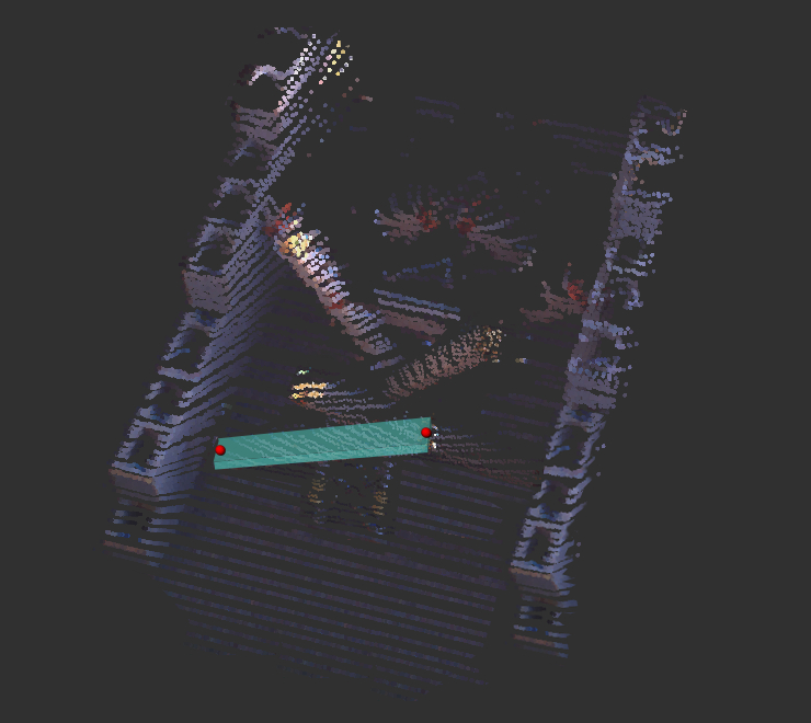
During motion planning, one risk comes from long objects that were partially occluded before the robot extracts them from the pile. If the end of a piece of lumber is unknown to the motion planner, the robot might strike itself or the environment when trying to move the object. This can be mitigated by having the perception system re-scan the object after pulling it off the pile. Or the human operator can specify the length of the object by selecting two points with the mouse (Fig. 3).
 |
 |
Results & Discussion:
The are various potential improvements to the perception system. Using a stereo camera or TOF sensor that outputs a structured point cloud would enable the use of faster algorithms that leverage the lattice (graph) relationship of the 3D points. Instead of fitting specific shape primitives like a cuboid or cylinder, it may be sufficient to compute the MVBB (Minimum Volume Bounding Box) for a small region of points. However without segmentation the box fitting can be biased by noise or points from other objects. There are also approaches that fit superquadrics to point clouds.
Tracking the robot’s gripper position would decrease the risk of failed grasps due to compliance in the robot’s arm or errors in lidar-to-gripper calibration. Also, tracking the pose of previously detected objects in the debris pile would negate the need to re-scan the scene before grasping each object.
There are some factors that impacted on planning the arm motions. When extracting an object from the debris pile, the robot’s 7-DOF arm is constrained by the position of the base, which is positioned in an approximate location chosen by the human operator. If a grasp motion fails because it’s unreachable using the arm, using a planner combining the arm and base DOF would solve that problem. Furthermore the planner only supports pre-grasp and post-grasp motions along a straight-line constraint, whereas in reality the constraint manifold should have some tolerance that looks more like a cone shape.
When moving an object to the side, the region where the object can be dropped is constrained by the length of the arm and the need to release long objects so that they fall within that region. This constrained motion plan was time-consuming to compute. In the DARPA Robotics Challenge this motion planning problem was easier for robots that had an extra rotation joint in the waist.
This work was conducted with help from my colleagues in Tartan Rescue at CMU.
| References: |
|
[1] G. C. Haynes, D. Stager, A. Stentz, B. Zajac, D. Anderson, D. Bennington, J. Brindza, D. Butterworth, C. Dellin, M. George, J. Gonzalez-Mora, M. Jones, P. Kini, M. Laverne, N. Letwin, E. Perko, C. Pinkston, D. Rice, J. Scheifflee, K. Strabala, J. M. Vande Weghe, M. Waldbaum, R. Warner, E. Meyhofer, A. Kelly and H. Herman, “Developing a Robust Disaster Response Robot: CHIMP and the Robotics Challenge”, Journal of Field Robotics, Vol. 34, No. 2, March 2017.
|
|
[2] K. Sjoo, A. Aydemir, T. Morwald, K. Zhou and P. Jensfelt, “Mechanical support as a spatial abstraction for mobile robots”, in Proceedings of the IEEE/RSJ International Conference on Intelligent Robots and Systems (IROS), October 2010.
|
|
[3] T. Simeon, J. Laumond, J Cortes and A. Sahbani, “Manipulation Planning with Probabilistic Roadmaps”, The International Journal of Robotics Research (IJRR), Vol. 23, Issue 7-8, August 2004.
|
|
[4] L. P. Kaelbling and T. Lozano-Perez, “Hierarchical Task and Motion Planning in the Now”, in Proceedings of the IEEE International Conference on Robotics and Automation (ICRA), May 2011.
|
|
[5] R. Schnabel, R. Wahl and R. Klein, “Efficient RANSAC for Point‐Cloud Shape Detection”, Computer Graphics Forum, Vol. 26, Issue 2, May 2007.
|