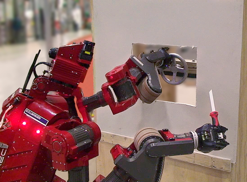
It would be useful for an inspection or service robot to be capable of opening or closing a hydraulic valve. If a fluid or gas is leaking, the robot could enter a hazardous area and shut-off the pipe. If there is a gas pressure build-up, the robot could open an outlet to vent the gas. This work describes a software system for an autonomous mobile manipulator robot to detect, grasp and turn hydraulic valve handles. The system was implemented using CHIMP (CMU Highly Intelligent Mobile Platform), a robot designed to perform maintenance tasks in dangerous environments [1]. For the DARPA Robotics Challenge, experiments were conducted using all types of hydraulic valves and we considered numerous situations where they might be encountered (Fig. 1).
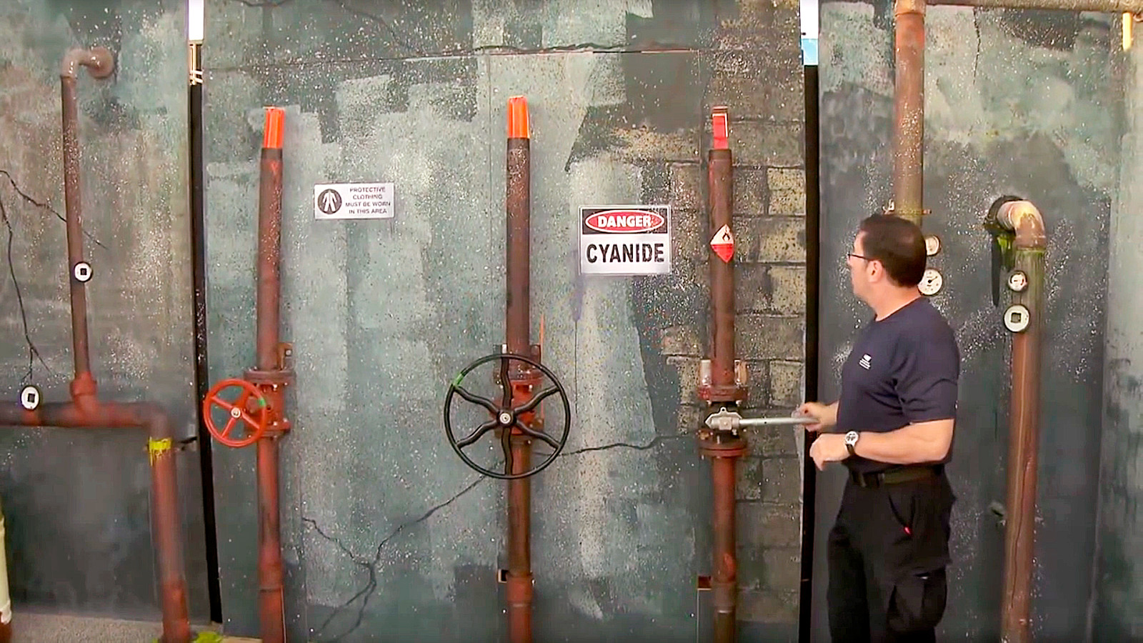
There are various types of valves that might be encountered in an industrial environment
A manual actuator is used to rotate the valve. A ball valve has a lever handle, of a size that increases with larger pipe diameters. A gate valve has a circular wheel handle, which either has variable-height during rotation (non-rising stem) or fixed-height (rising stem).
When thinking about robot perception or motion planning, the wheel handle on a valve is similar to the steering wheel in a car or UTV. However, typically a large initial torque is required to start opening a valve that has been tightly closed. On a non-rising stem valve, the handle moves further away from the valve as it’s turned, so the robot’s gripper position will need to change along two axes. A rising-stem valve is easier for motion planning because the handle only rotates, however the stem thread pushes through the handle which means the robot must keep its gripper away from this area.
(left) Red-colored 10.2″ wheel handle on a 3″ gate valve (non-rising stem).
(center) Black-colored 18″ wheel handle on a 3″ gate valve (non-rising stem).
(right) A 13″ lever on a 3″ ball valve.
In this work we focus on the perception and manipulation of circular wheel handles of various diameter. For simplicity, an aluminum wheel is attached to the wall in the center by a bolt. The wheel moves by pure rotation of 0-2 turns in the clockwise or counter-clockwise direction, with negligible force or motion constraints imposed by a screw thread or valve mechanism. The wheel handle is effectively a simplified steering wheel.
We did do some testing using one heavy-duty cast iron non-rising stem gate valve, shown in Fig. 16 below. As the red wheel handle is rotated, it moves inwards towards the robot.
Related Work:
There is potential for computer vision to improve tasks like inspection or asset management, where a worker needs to regularly walk around a facility and check the existence or state of various pieces of equipment. Various work has looked at detecting shape primitives such as lines, circles and ellipses [3]. Pang and Neumann developed a system to detect known object models like valves in a point cloud of an industrial environment [4].
With respect to manipulation, multiple groups have previously invented mechanical devices for turning the steering wheel in a car, in order to compete in the first DARPA Grand Challenge for autonomous driving in 2004.
Konno et al. discuss strategies for a humanoid robot to apply sufficient force for manipulation tasks and made the robot turn a lever handle using SQP (Sequential Quadratic Programming) [5].
Mishra et al. considered the problem of manipulating small wheel handles [6]. The robot is positioned such that the camera is perpendicular to the valve and simple computer vision techniques are used, like color-based segmentation and edge detection.
Robot Platform:
CHIMP has a panomorphic (fisheye + anamorphic) camera and 2 spinning LiDAR sensors to provide immersive 360° perception. These sensors are calibrated to output a coherent point cloud.
The robot has two 7-DOF position-controlled arms, each with a Robotiq 3-finger adaptive gripper. Each joint has continuous rotation, with a torque-tube and clutch on the output shaft that enables some compliance. The arms generally have good positional repeatability, however each joint position is measured on the motor-side of the actuator. The Robotiq gripper was modified for increased durability, including tougher internal gears and wiring re-routed through the wrist. Overall the gripper and arm are very robust and can provide significant torque on the wheel handle.
Valve Pose Detection:
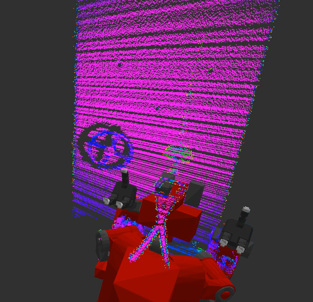
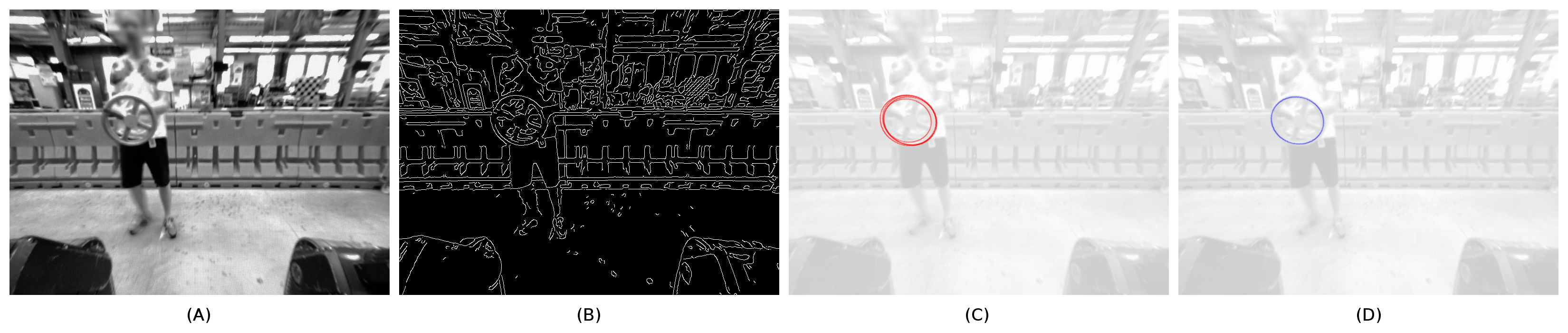
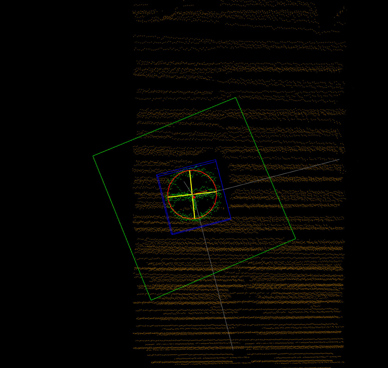
Red circle = detected valve pose.
This section describes 3 perception algorithms for detecting the 3D pose of a circular wheel handle in the scene. The general approach is essentially just ellipse detection (in a 2D camera image) or circle fitting (in a 3D point cloud from LiDAR scanner).
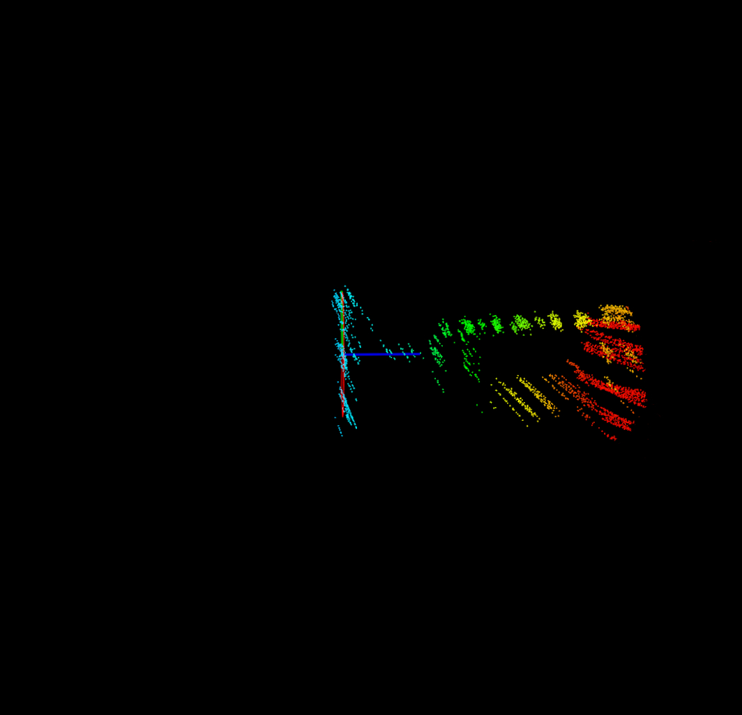
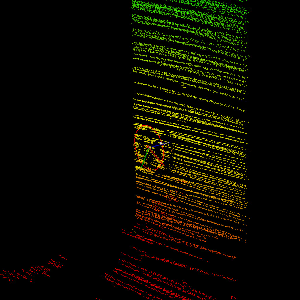
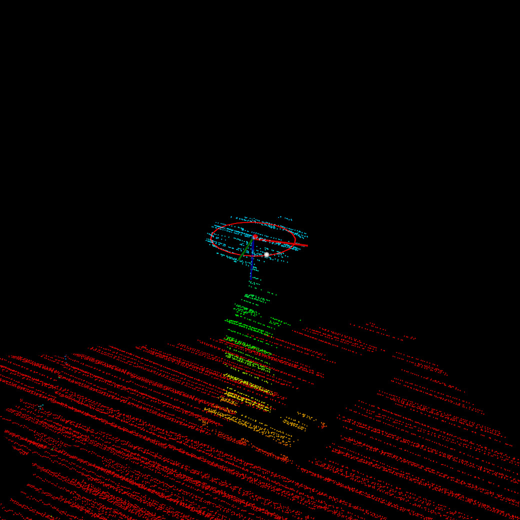
There were 2 interesting challenges for detecting circles in the 3D point cloud. If a wheel handle is in front of a wall, the LiDAR sensor casts a shadow against the wall (Fig. 3). A circle-fitting algorithm will detect both the wheel and the shadow of the wheel. Secondly, the spinning LiDAR does not produce a dense point cloud of the wheel handle. The LiDAR uses a “lapping” pattern that creates horizontal stripes in the resulting point cloud, where the points are high-density in the horizontal direction and low-density in the vertical direction (Fig. 4). Also, the depth measurement error of the LiDAR (+/- 30 mm) results in high-density points along the angle of incidence (Fig. 4). This means it’s important to down-sample the pointcloud using a voxel grid filter.
The 3 algorithms are described below in detail:
1. Automatic detection:
Sensors used: Camera + LiDAR.
This method detects ellipses in the camera image using the method in [3] and the final pose is refined using the LiDAR point cloud.
- Pre-processing (convert RGB image to perspective projection, histogram equalization, normalization, convert to grayscale).
- Detect edges (gaussian blur, Canny).
- Find contours [7].
- Detect ellipse candidates [3].
- Get best 2 ellipse candidates (number of edge pixels, similar center point).
- Compute best ellipse (middle of inner and outer ellipse).
- Project 3 points from ellipse into the 3D point cloud.
- Fit 3D circle to the point cloud.
 |
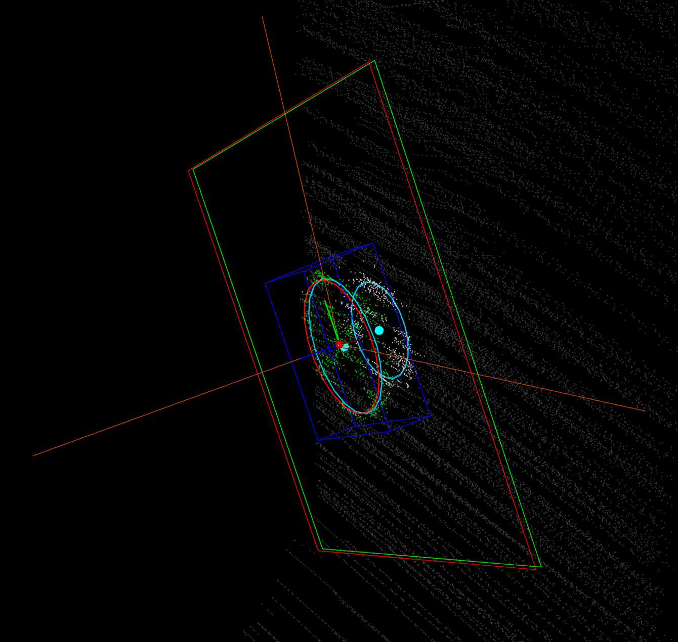
2. User-guided (2 clicks + axis constraint):
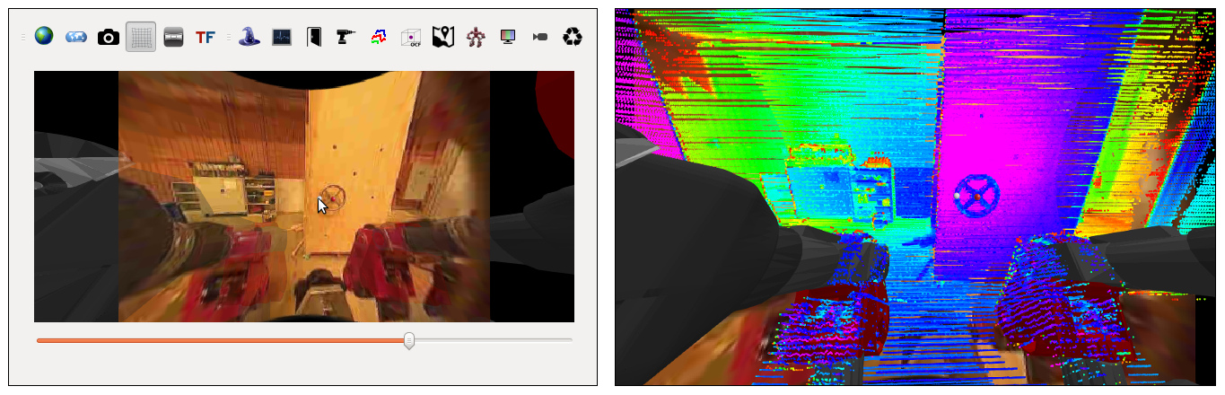
Sensors used: LiDAR + camera for visualization.
The human operator can see through the robot’s “eyes” by looking at a 2D or 3D projection of the fused input from the camera and/or LiDAR sensors. After identifying the valve handle in the scene, the operator selects the valve using 2 mouse clicks. The first click must be at the center of the wheel, on the axis of rotation. The second click must be on the circumference of the wheel, in-between two of the spokes. The operator also selects some parameters: valve type (horizontal, vertical) and grasp type (center, circumference). The core of the algorithm only uses the LiDAR pointcloud.
- Human operator specifies a vertical or horizontal valve type.
- Operator clicks 2 points (valve center and circumference between spokes) on the camera image or LiDAR point cloud.
- Project 2 points into the 3D point cloud.
- Compute vector between 2 points.
- The valve pose is defined by this vector and the axis constraint vector.
- The grasp pose is located at the 2nd click point.
- Refine pose by fitting circle to 3D points using RANSAC.
 |
 |
 |
3. User-guided (1 click):
Sensors used: LiDAR + camera for visualization.
This is similar to method 2, except the human operator only needs to click one point using the mouse. This algorithm automatically detects valve wheel handles that are horizontal, vertical, or at some angle.
- Human operator clicks 1 point (valve center) on the camera image or LiDAR point cloud.
- Project point into the 3D point cloud.
- Crop point cloud in sphere around the click point, with fixed radius of largest expected valve.
- Iteratively fit all circles to the set of 3D points using RANSAC.
- Sort circles (distance of circle center to click point, number of inlier points).
- Keep the best circle.
- The valve pose is defined by the 3D circle, with a normal vector pointing towards the robot.
- Crop point cloud in cylinder inside the circle circumference.
- Run PCA (Principal Component Analysis) on the 3D points of the wheel spokes.
- The grasp pose is located on the circle circumference, in-between the axis found by PCA.
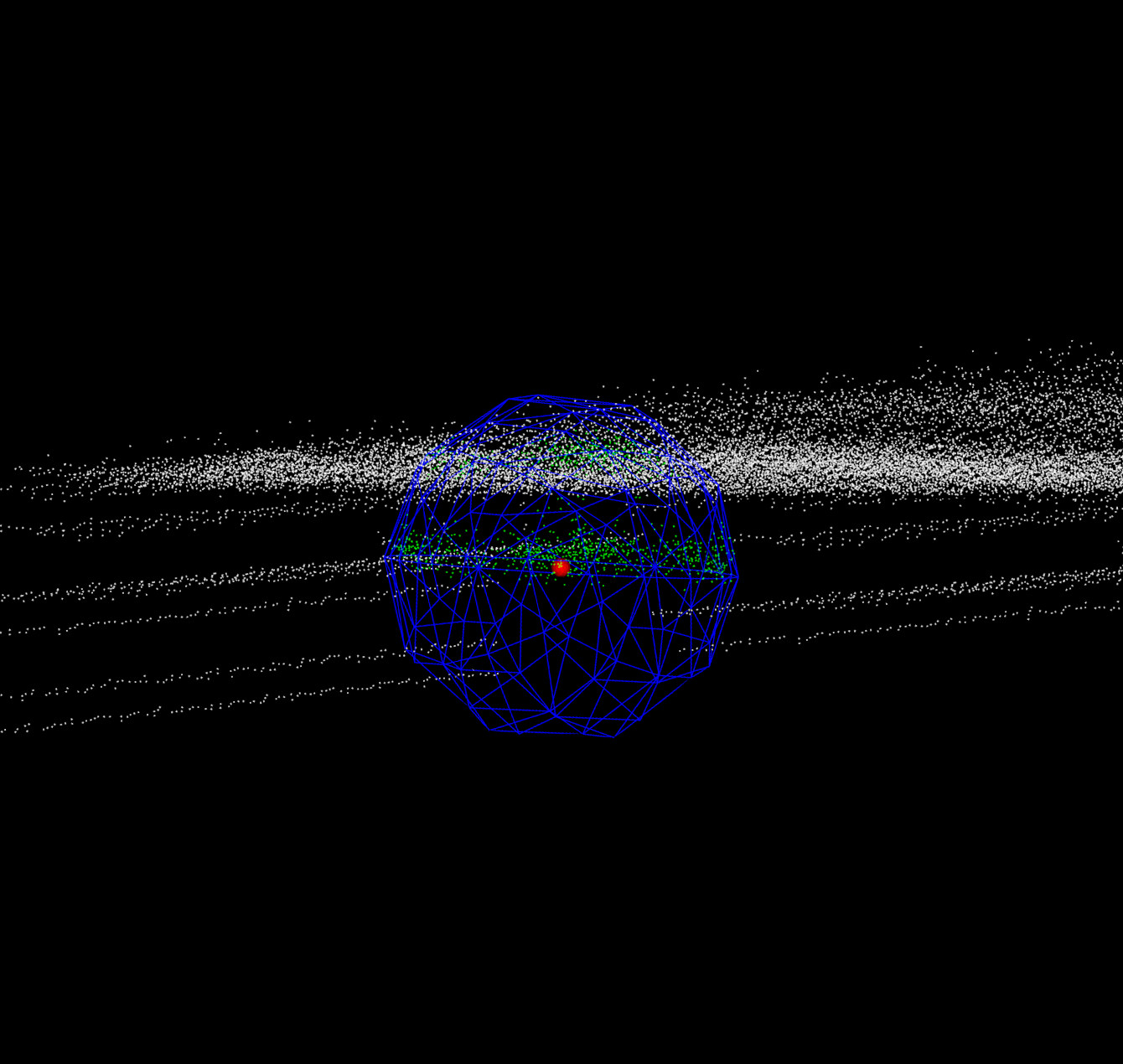 |
 Red = the best-fit circle and detected pose. |
 |
 |
Grasping:
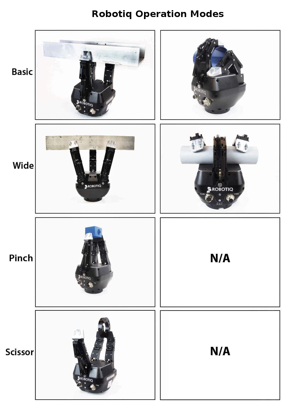
The Robotiq 3-finger adaptive gripper has 4 modes of operation (Fig. 13) primarily used to set the finger-spread. Each finger has 3 joints that are underactuated, meaning that each finger can be set to either: “open”, “close” or approximately halfway open (finger straight).
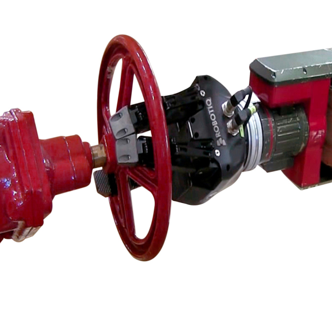
Various grasps (gripper configurations) were considered for turning a valve, depending on the diameter of the wheel handle (Table 1). Most wheel handles can be grasped on the circumference. In a real-world scenario the valve would require significant torque to start rotating and a two-handed grasp might be necessary. For the simplified case of turning a wheel with negligible torque we considered other types of grasps, such as using one finger to “poke” or two-fingers in a “pincer” configuration. For these grasps the finger(s) remain straight after inserting them in-between the cross-braces (spokes) of the wheel handle.
| No. of hands | Grasp type | Robotiq gripper mode | Grasp location | Example |
| 2 | Power – wrap | Basic | On circumference, like a steering wheel. |
 |
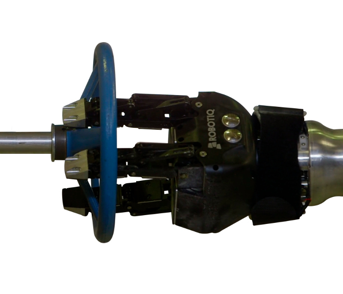
| 1 | Power – wrap | Basic | On circumference |
 |
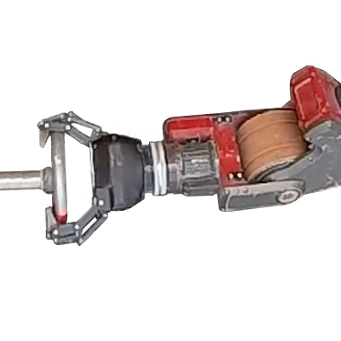
| 1 | Point / poke (middle finger straight) |
Basic | In-between spokes, near circumference. |
 |
| 1 | Pincer (fingers half open) |
Pinch | On center-axis |
 |
| 1 | Tripod (fingers half open) |
Wide | On center-axis |
 |
| 1 | Power – spherical | Wide | On center-axis |
 |
Motion Planning:
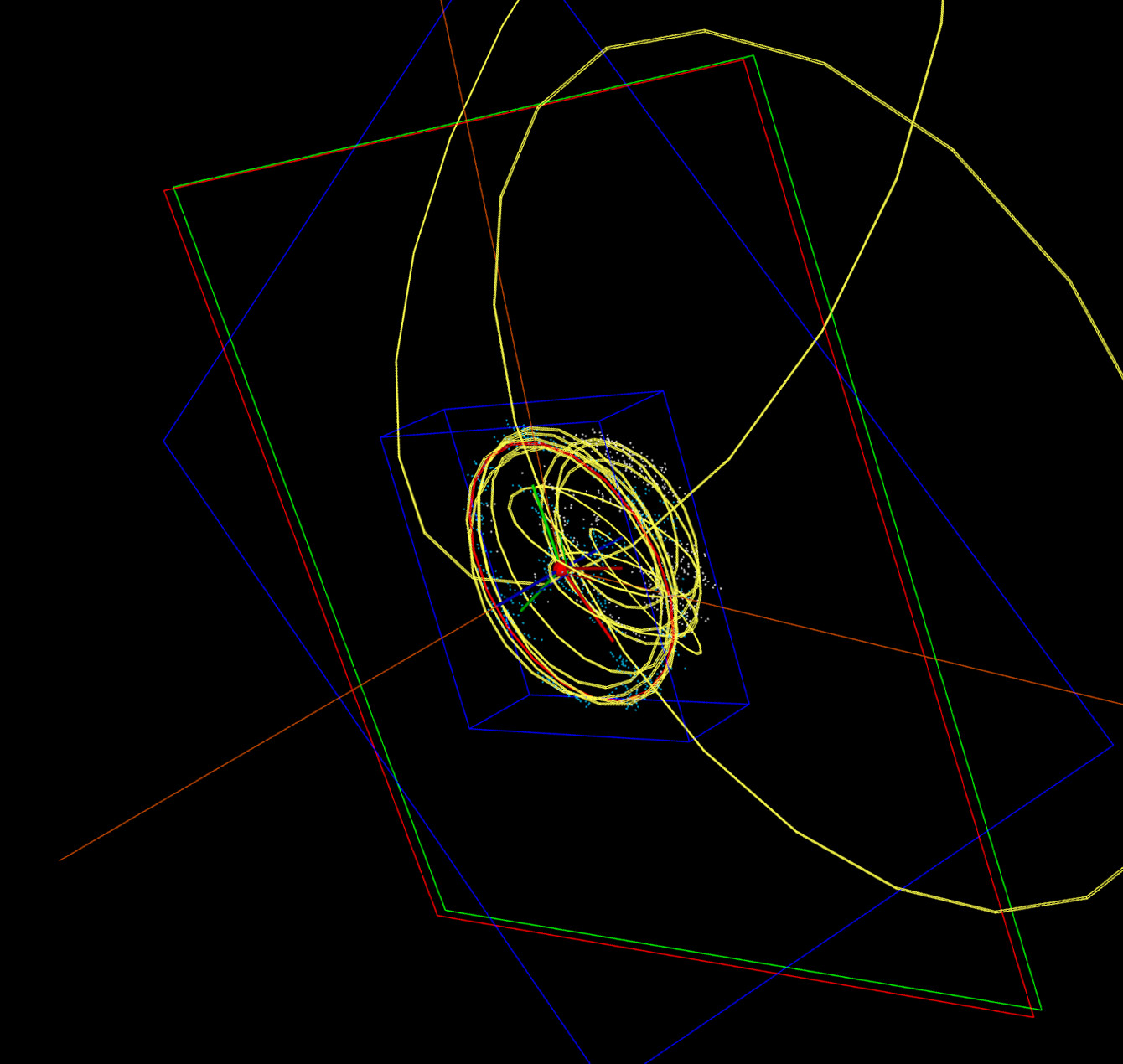
Depending on the grasp type, the gripper must either follow a circular path along the circumference of the wheel or simply rotate the wrist joint on the wheel’s axis. The most difficult aspect is planning motions for the arm such that the gripper traces a circular path. The problem is made easier by allowing a larger tolerance along the path, by maintaining a loose grasp with the gripper, and due to compliance in the robot’s arm joints. For larger-diameter wheels we found that rotating the grasp pose inwards towards the axis-of-motion reduces the overall motion of the 7-DOF arm and reduces planning time.
For circumference turns, the rotation motion constraint is represented using a TSR (Task Space Region) [8] and the constrained motion planning problem is solved using the CBiRRT2 algorithm [8]. Each joint in the robot’s arm allows for continuous rotation, however currently the motion planner assumes each joint can only rotate +/- 180°. For center-axis turns, the rotation motion is simply interpolation of the wrist joint angle. Arm motions with basic gripper pose constraints or linear motion constraints are planned using the RRT-Connect algorithm [9].
During motion planning, collision-checking is performed between the robot’s geometry and the environment. The robot’s geometry is represented using multiple intersecting bounding boxes (cuboids), which is more efficient than a polygon mesh. The environment is modelled using a voxel grid, with a higher-resolution sub-grid in the local area around the detected valve.
The gripper is expected to be in-collision when grasping or turning the wheel, therefore a disc-shaped region of voxels are temporarily removed during these phases of planning. An alternative approach would be to replace those voxels with a known 3D model of the wheel, thus enabling gripper-to-object collision checks to be turned on/off as required.
Planning the complete motion to turn the valve means combining a sequence of collision-free motion plans generated by the individual planners. This meta-plan consists of the following actions:
- Move gripper from current pose to pre-grasp pose.
- Set gripper pose (open fingers).
- Move gripper from pre-grasp pose to grasp pose, constrained along a line.
- Close gripper fingers (grasp).
- Either: Move gripper to turn handle, constrained along a circular path.
or: Rotate wrist join. - Open gripper fingers.
- Move gripper from current pose to post-grasp pose, constrained along a line.
- Move arm to ‘home’ position.
Results & Discussion:
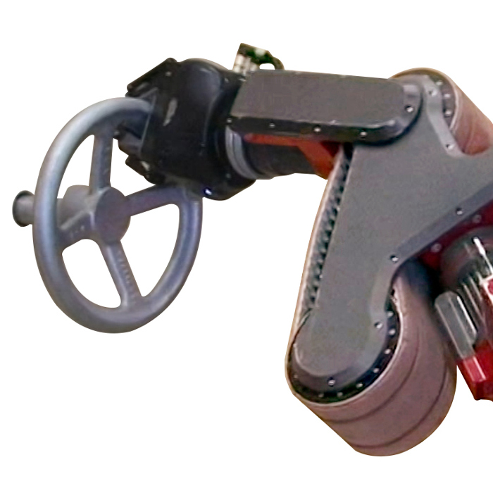
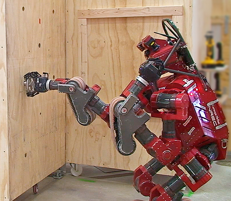
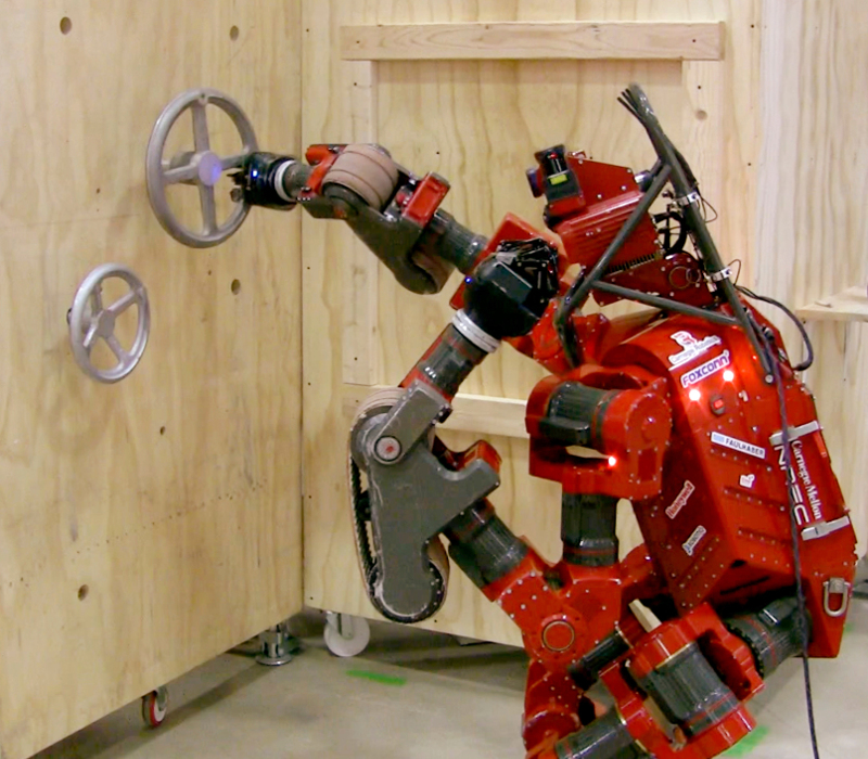
The system was successfully used to detect valve wheel handles of various sizes and to turn the handle using different grasp types (Fig. 14-17). The smallest wheel handles (Fig. 14) or handwheels require a power-spherical or partial wrap grasp. The medium-to-large wheel handles can be turned by grasping on the circumference using one arm (Fig. 15-16). As the wheel gets larger, requiring a larger circular path constraint, the 7-DOF arm has to move within a larger volume of space. This makes it more complicated to find a motion plan that is kinematically-feasible along the entire constraint, which means the position of the robot’s base is critical.
 |
 |
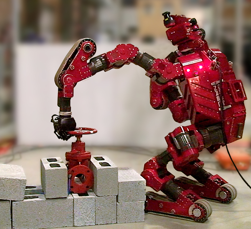 |
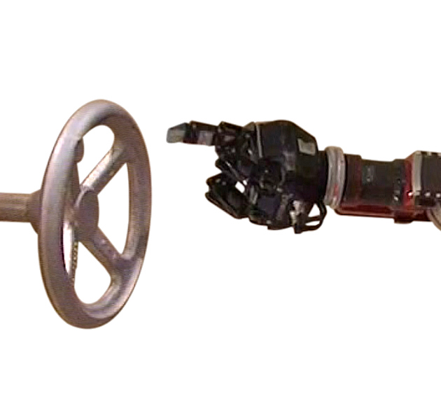
For these experiments the valve apparatus has almost zero friction, requiring negligible torque to turn the handle. Therefore most of the wheel handles can also be turned using a pincer grasp on the center-axis (Fig. 17). This is useful because it’s faster to compute a motion plan with only wrist rotation, compared to a circular path constraint.
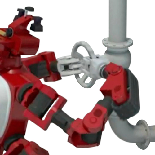
We also performed some simulation experiments of turning a wheel using two arms, which is how a human can apply sufficient torque to open a ‘stuck’ valve. In contrast to the one-arm approach, the robot base is positioned such that both arms have an equal volume of reachability. The kinematics of this task requires the robot to re-grasp the wheel to make successive turns, which greatly increases the time for motion planning.
At the DARPA Robotics Challenge Finals the human operator manually positioned the robot near the valve, using the help of visual guides overlaid of the robot’s 3D world view. These guides indicate the center of the kinematic reachability volume for each arm. To detect the valve we used algorithm #2 (two click method), for speed and reliability. There was some concern that using the camera image could be unreliable in an outdoor environment, with varying levels of brightness, therefore we used only the LiDAR sensor for perception. The two-click method specifies the exact position to grasp on the wheel circumference, which is useful because our automatic spoke detection algorithm is not robust for all types of wheel handles. Once the operator’s input is received, the pose of the valve is returned almost instantly.
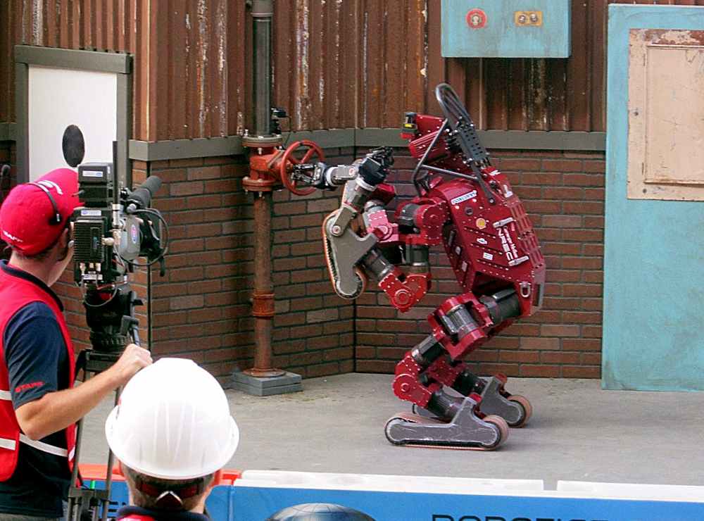
At the competition the CHIMP robot successfully turned a 10.2″ (260mm) wheel handle using a “pincer” type grasp (Fig. 17). On day 1 there was some error in the position of the gripper with respect to the valve, caused by lost calibration of the right arm joints. The robot had previously fallen on its right arm which caused clutch-slip on the output shaft of some of the joints. However, the robot’s overall strength, the robustness of the gripper, and the compliance in the arm joints meant that it could still rotate the wheel handle.
On day 2 the valve grasp was more accurate, with only a slight mis-alignment of the gripper with respect to the valve, due to some “drift” in the gripper-to-map frame relation from CHIMP’s localization system. CHIMP was the only robot that built a coherent “world” map of the environment, updated on-line as it was moving around. Other robots were doing perception and manipulation based on what the robot could “see” directly in front.
Future work will be to:
- Detect 2-5 spokes of any wheel handle using 3D line model and RANSAC.
- Fit 3D model of known wheel handles.
- Add support for continuous-rotation joints in motion planner.
- Develop a combined arm-and-base motion planner.
- Compare torque applied by robot, for different grasp types (circumference Vs. rotate wrist).
- Plan arm motion for maximum applied torque, if a valve is tightly closed.
This work was conducted with J. Gonzalez-Mora, K. Strabala, C. Dellin and E. Perko at CMU (Carnegie Mellon University)
and NREC (National Robotics Engineering Center).
| References: |
|
[1] G. C. Haynes, D. Stager, A. Stentz, B. Zajac, D. Anderson, D. Bennington, J. Brindza, D. Butterworth, C. Dellin, M. George, J. Gonzalez-Mora, M. Jones, P. Kini, M. Laverne, N. Letwin, E. Perko, C. Pinkston, D. Rice, J. Scheifflee, K. Strabala, J. M. Vande Weghe, M. Waldbaum, R. Warner, E. Meyhofer, A. Kelly and H. Herman, “Developing a Robust Disaster Response Robot: CHIMP and the Robotics Challenge”, Journal of Field Robotics, Vol. 34, No. 2, March 2017.
|
|
[2] Photo based on “DRC Task: Valve”, DARPA (Defense Advanced Research Projects Agency), 2013.
http://www.youtube.com/watch?v=T5No8jgDp5E |
|
[3] T. M. Nguyen, S. Ahuja and Q. M. J. Wu, “A Real-Time Ellipse Detection Based on Edge Grouping”, IEEE International Conference on Systems, Man and Cybernetics, October 2009.
|
|
[4] G. Pang and U. Neumann, “Training-Based Object Recognition in Cluttered 3D Point Clouds”, International Conference on 3D Vision (3DV), July 2013.
|
|
[5] A. Konno, Y. Hwang, S. Tamada and M. Uchiyama, “Working Postures for Humanoid Robots to Generate Large Manipulation Force”, IEEE/RSJ International Conference on Intelligent Robots and Systems (IROS), August 2005.
|
|
[6] P. Mishra, H. N. Shankar, J. S. Bhat, S. R. Kubair, S. H. Bharadwaja, S. Anudhan, D. K. Hundi and G. Kamath, “Multi-sensor Autonomous Robot Based Manipulation of Valves for Process Control”, Third Asia International Conference on Modelling & Simulation, May 2009.
|
|
[7] S. Suzuki and K. Abe, “Topological Structural Analysis of Digitized Binary Images by Border Following”, Computer Vision, Graphics and Image Processing, Vol. 30, Issue 1, April 1985.
|
|
[8] D. Berenson, J. Chestnutt, S. Srinivasa, J. Kuffner and S. Kagami, “Pose-Constrained Whole-Body Planning using Task Space Region Chains”, Proceedings of the IEEE-RAS International Conference on Humanoid Robots (Humanoids), December 2009.
|
|
[9] J. J. Kuffner and S. M. LaValle, “RRT-Connect: An Efficient Approach to Single-Query Path Planning”, Proceedings of the IEEE International Conference on Robotics and Automation (ICRA), April 2000.
|